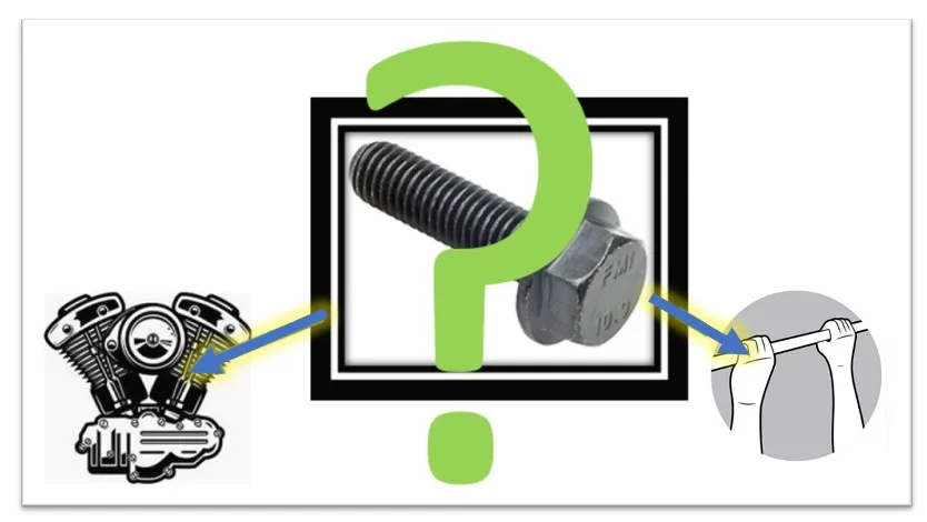
Simulation 2020: Is a bolt stiff like an engine or flexible like your hands?
Simulation 2020:
Is a bolt stiff like an engine or flexible like your hands?
In all versions of SOLIDWORKS Simulation, Remote Loads can be created using two connection types: Rigid and Distributed.
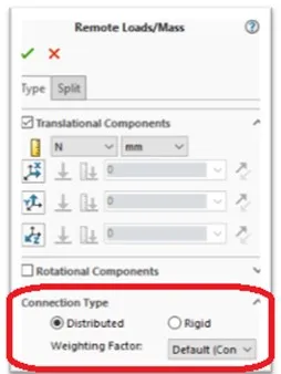
Figure 1 – Remote Load
Now with Simulation 2020, we can use these same two options with Bolt and Pin connectors as well.
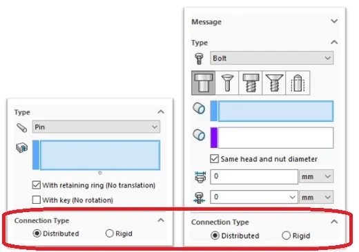
Figure 2 – Bolt and Pin connectors
DISTRIBUTED CONNECTORS COMPARISON STUDIES
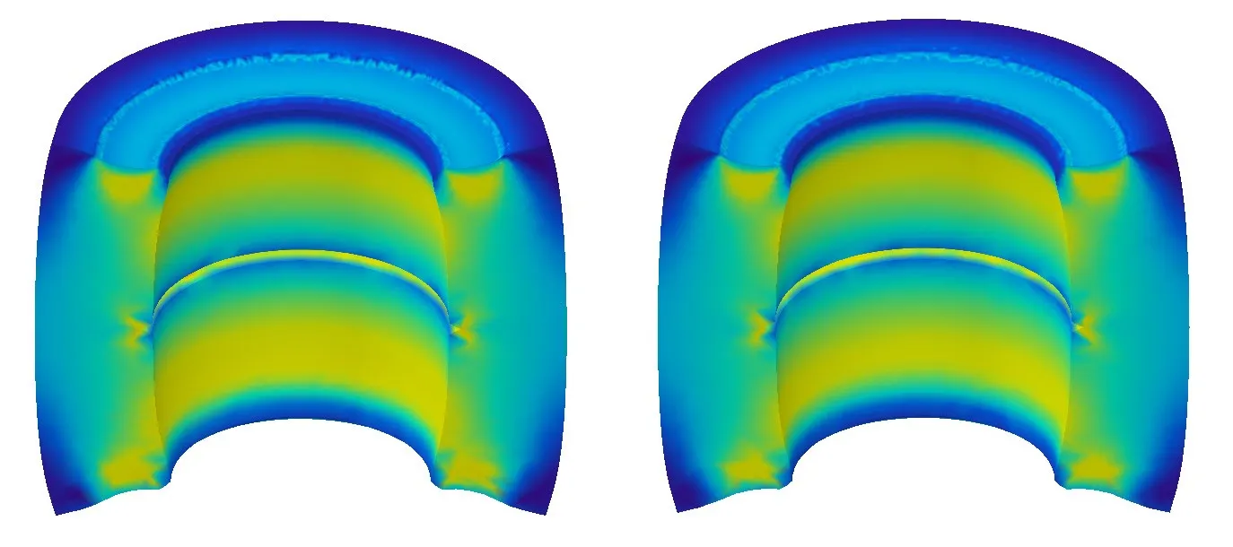
To see the difference between these options, I’ve run a few comparison studies to illustrate what they are doing. Can you tell the difference between these two stress plots?
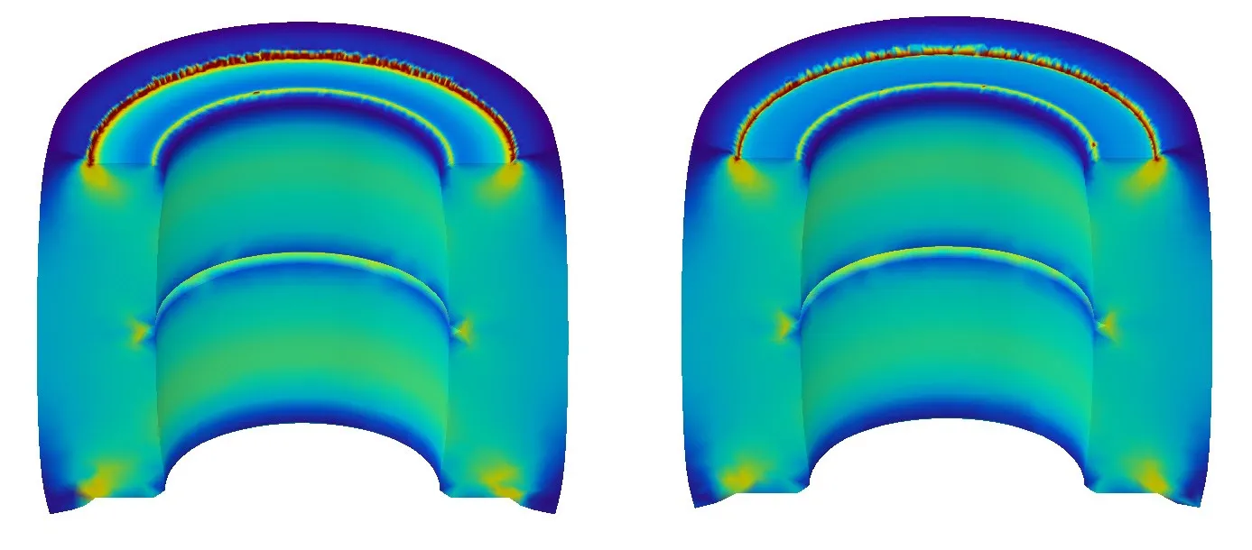
The picture on the left was created using a RIGID connection type (available in 2019 and prior). Notice this plot looks almost identical to setting up a study using prescribed displacements (right; see figure 3).
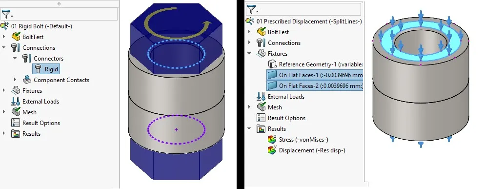
Figure 3 – Rigid Bolt vs Prescribing displacements
The RIGID option has behavior that is similar to mounting an engine inside a vehicle. The engine is stiff compared to the vehicle frame so we can simplify the engine as a point-mass and use rigid bars to connect it to the frame. The engine stiffens the frame considerably.
What about these two stress plots? Is there much of a difference?
The picture on the left was created using the new DISTRIBUTED connection type which you can see is practically equivalent to simply applying a uniform load to the faces in this case (right; see figure 4).
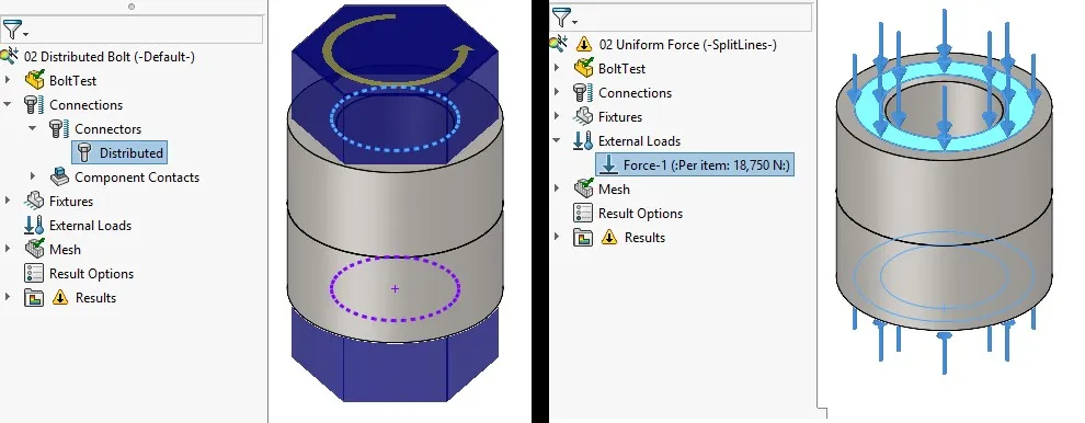
Figure 4 – Distributed bolt vs. uniform load
The DISTRIBUTED option has behavior like your bodyweight hanging from a pull-up bar. Your hands don’t add any stiffness to the bar.
Does a bolt behave more like the engine, or is it more flexible like your hands?
This last stress plot (figure 5) shows a physical bolt being modeled, meshed, and shrunk into place (this is a common FEA technique to model bolts with preload directly) so we can compare. What do you think?
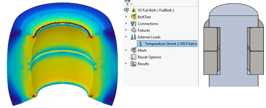
Figure 5 – Bolt model with temperature shrinkage trick
The new DISTRIBUTED option seems to do a better job in this case, but the choice can sometimes be a tricky one. For more technical information, these elements were inspired by the Distrubuted and Kinematic coupling elements used in Abaqus.
Interested in learning more about what’s new in SOLIDWORKS 2020, check out our collection of videos here.

About Shaun Bentley
Shaun Bentley is passionate about applied mathematics and engineering, which led him to pursue and understand real world applications of FEA, CFD, kinematics, dynamics, and 3D & 2D modeling. He teaches many simulation classes to both new and advanced users attending training at GoEngineer. Since 2006, Shaun has been working with simulation tools to solve real world engineering problems. With every new project, he seeks to find ways to push simulation to its uppermost limits, even going so far as to write bespoke code and macros. He has passed the Michigan FE exam and mentors or consults for virtually any industry that uses SOLIDWORKS, especially automotive and automated tools. He is a speed 3D modeling champion and one of the first Certified SOLIDWORKS Experts in Simulation in the world.
Get our wide array of technical resources delivered right to your inbox.
Unsubscribe at any time.