How to Design an Assembly in SOLIDWORKS for 3D Printing
Engineers strive to make designs faster, better, cheaper, and lighter. Some might say we do this to the point of obsession. Before additive manufacturing, (otherwise known as 3D printing), the only way to create a prototype was through subtractive manufacturing, where a block of material was cut away until only the designed part, or injection molded part was left.
Not only was this prototyping method slow and expensive, but components could only be produced and assembled one at a time. Creating single part files one at a time through both subtractive and injection molding manufacturing methods is still used today, but the development of 3D printing, producing moving assemblies with many articulating components working together, is faster and easier.
Leave Air Gaps
When a Stratasys 3D printer receives a SOLIDWORKS file with overlapping or touching geometry, it will print the two or more parts together as if they were one component. That is not ideal for a real-life moving assembly with separate components that articulate against one another.

Double-check your models to make sure there is space between all parts in the assembly. The rule of thumb is that the air gaps should be at least double the layer thickness of your choice, which can be specified before the print. This allows the gap to be small enough to be unnoticeable at a glance but large enough for the soluble support material that fills the gap during the printing process to be washed away.
For example, I modeled in SOLIDWORKS an adjustable wrench and will print it using a Stratasys F170 FDM 3D printer.
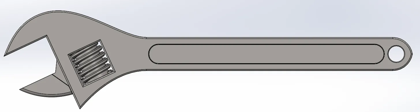
3D CAD model with gaps created in SOLIDWORKS
I chose the smallest layer thickness possible (0.005”) so I needed at least a 0.01” air gap between all of my adjustable wrench’s component faces. There is now no risk that the extruded paths of the FDM printer will melt together while printing.
One could argue that with the variety of materials and printing solutions available that the air gaps could increase or decrease, which is true, but in most cases, using the best practice of doubling the air gap compared to the layer thickness of the 3D printed assembly will work as intended.
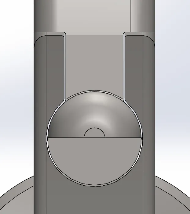
All separate components have a .01” gap between them
Soluble Support Material
After you’ve set up your model, you’ll want to use a 3D printer with a dual extruder, where one extruder is for model material and the other is for support material. The support material is used to help support any overhanging/undercuts in your model, but in an assembly, it will help maintain the gap between your components.
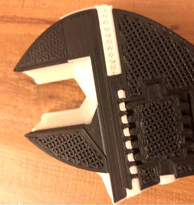
Unfinished 3D printed adjustable wrench with support material shown in gaps between articulating components
The nice thing about support material, is that most are water soluable for plastic printers. All you have to do is put your parts in a solution bath, and eventually all of the support material will be removed from your assembly. The bath for a fully assembled 3D print can often take longer than for a single component 3D print because the air gaps between components are small, thus taking the bath longer to penetrate. In the case of this 3D printed adjustable wrench, the support material took nine hours to wash away at 85 degrees Celsius.
Most support material is water-soluble for plastic printers; put your parts in a solution bath and the support material will get removed from the assembly. Bath time is longer for a fully assembled 3D print versus a single component print because the air gaps between components are small, thus taking the bath longer to penetrate. In the case of my 3D printed adjustable wrench, the support material took nine hours to wash away at 85 degrees Celsius.
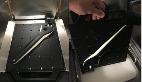
3D print when finished and placing the 3D print into a soluble water bath
After the 3D print has been thoroughly washed and only model material is left, gently move the parts around to pry them further apart and generate the desired movement of the assembly. It's important to be gentle; too much force will cause delicate parts of the assembly to snap.
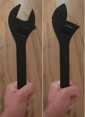
3D print with the movement of the component seen.
Keep in mind that when designing assemblies, even if you have adequate air gaps between various part files of the assembly if the holes leading out to the water bath are too complicated, the soluble support deep in the model may never come in contact with the bath. The support material in these gaps will not dissolve enough for the components to move, no matter how long the assemble is in the bath. For my adjustable wrench example, I had to move the knurl and the replacement jaw a lot to finally loosen the remaining support material in the small gaps of the wrench that had not been washed away.
Finally, remember that there can be drawbacks to printing your assembly as one print. If you want to print your components in different materials, colors, or finishes then you will still need to print those parts separately and assemble it afterward.
More Design Projects
Creating a 3D Printed Race Medallion Hanger Using SOLIDWORKS
Designing a 3D Printed Storage Box Using Multi-Bpdy Part Modelling in SOLIDWORKS
Optimizing Golf Design Using SOLIDWORKS Tools
A Modern Take on a Classic: 3D Printed Fender Telecaster

About Taran Packer
Taran is a SOLIDWORKS Simulation Technical Support Specialist at GoEngineer. He has a Bachelor’s degree in Biomedical Engineering from the University of Utah. Taran enjoys learning about different tools in SOLIDWORKS Simulation, Flow Simulation, and Plastics.
Get our wide array of technical resources delivered right to your inbox.
Unsubscribe at any time.