SOLIDWORKS Simulation - Water Pressure Load
SOLIDWORKS Simulation is capable of simulating a nonuniform pressure gradient. This allows for a
simulation setup on a model that would approximate the pressure of water on the inside of a tank
or against a dike.
Nonuniform Pressure Requirements
A nonuniform pressure has the following requirements:
- A “Reference Coordinate System”
- Faces on which to apply the pressure load
- An equation by which to define the pressure as a function of coordinate variables
Each of these will need some fine tuning to approximate a pressure load due to water as follows:
- The “Reference Coordinate System” placed at a location on the surface of the water/liquid with one of the coordinate directions (X, Y, or Z) in the direction normal to the water/liquid surface.
- The faces to apply the pressure load must be only those faces where the water/liquid touch. Faces partially submerged would need to be split into multiple faces using a “Split Line” command
- The equation for water/liquid pressure used would for static pressure depending on depth:
Pstatic fluid = ρgh
…where P = pressure, ρ = fluid density, g = acceleration of gravity, and “h” will be replaced
with the direction variable of the “Reference Coordinate System” set normal to the surface
of the water.
Example Study Setup
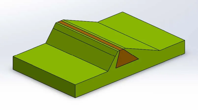
In this example the situation being studied is a potential design for a bi-material dike system
where water pressure will be placed on the steep face of the dike with no counter pressure placed
on the shallow back face of the dike. In this example the waterline is set to be part the way up the
dike face; a “Split Line” is generated to create this waterline. A cross sectional piece of the dike is
displayed in Figure 1.
In this setup the underside of the model is immobilized with a “Fixed” fixture condition and all the
cut faces used to create the section of the model are applied with “Symmetry” fixtures, as seen in
Figure 2, in order to allow the sectional model to behave as a large full model might.
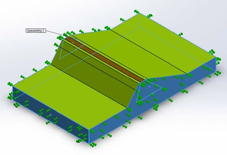
Figure 2: Cut faces of the model section with “Symmetry” fixtures defined.
A “Reference Coordinate System” (seen in Figure 3) is placed at the intended waterline of the
model in order to simplify the equation (no offset constant) that will then define the pressure
condition applied in the model and allow the coordinate system to move with the waterline.
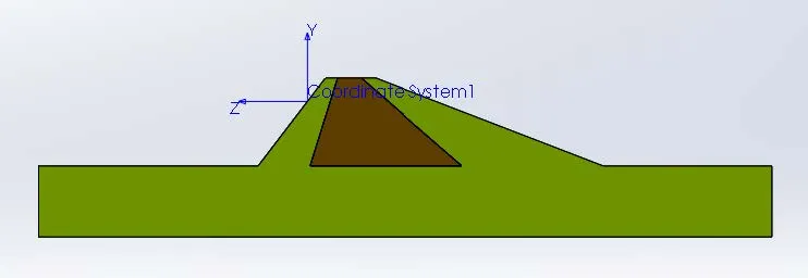
Figure 4: Nonuniform pressure definition.
The selected faces of the pressure load are the selected to be the submerged faces shown in
Figure 5.
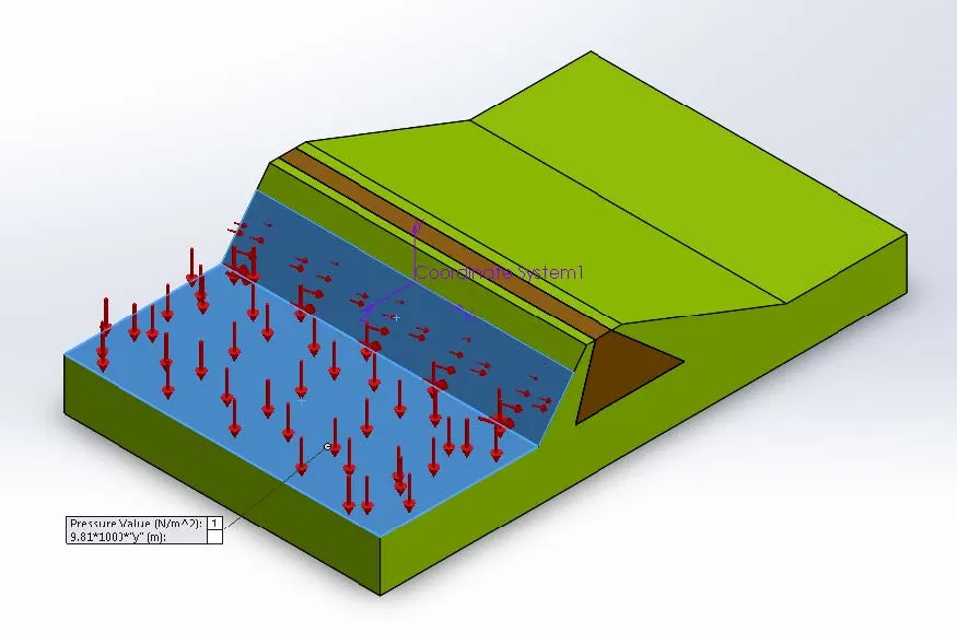
Figure 5: Selected faces for the nonuniform pressure load condition.
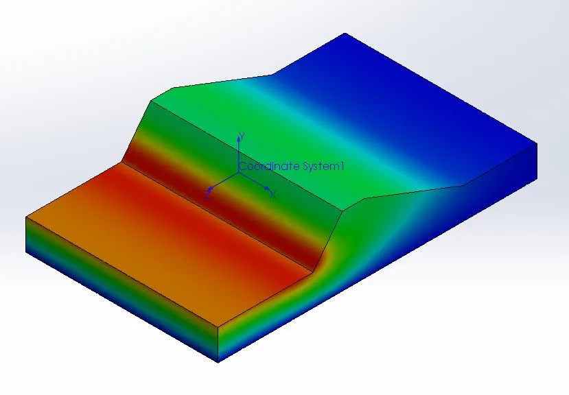
With these fixture conditions and the nonuniform pressure condition set the model is ready to run
and may show a displacement profile such as Figure 6.

About Ryan Dark
Ryan has been in the GoEngineer technical support team since February 2008 where he most notably provides support for all FEA and CFD software offered by SolidWorks. His most recent accolade is the title of Elite Application Engineer awarded by SolidWorks Corp.
Get our wide array of technical resources delivered right to your inbox.
Unsubscribe at any time.