Creating Angular Dimensions Using an Imaginary Line

Article by GoEngineer on Jan 28, 2018

What? Are you kidding? That was my reaction too.  Yes, creating an angular dimension without actual geometry can be done.  Anyone of us that has spent time just setting up a sketch with featureless construction geometry just to control an angle measured from the X or Y axis will appreciate this little ditty.

Below are the simple steps to accomplish this…

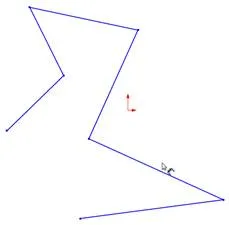
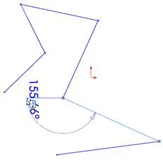
  • 1. We’ll start with a part file open and a sketch already in process.  Click Smart Dimension from the Command Manager Sketch tab.
Creating Angular Dimensions Using an Imaginary Line
  • 2. Select a line in the sketch or an edge in a drawing.
Creating Angular Dimensions Using an Imaginary Line
  • 3. Click a collinear vertex.
Creating Angular Dimensions Using an Imaginary Line
  • 4. You should see the crosshair appear, choose one of its segments and drag in the direction of where you want the angle dim to lie.
Creating Angular Dimensions Using an Imaginary Line
  • 5. You will see the preview as normal between the edge selected and the segment from the crosshair.
Creating Angular Dimensions Using an Imaginary Line
  • 6. Click to place the dimension.
Creating Angular Dimensions Using an Imaginary Line
  • 7. Adjust the dimension as needed.
Creating Angular Dimensions Using an Imaginary Line

Yup, that’s it.

Creating Angular Dimensions Using an Imaginary Line


About GoEngineer

GoEngineer delivers software, technology and expertise that enable companies to unlock design innovation and deliver better products faster. With more than 35 years' experience and tens of thousands of customers in high tech, medical, machine design, energy and other industries, GoEngineer provides best-in-class design solutions from SOLIDWORKS CAD, Stratasys 3D printing, Creaform & Artec 3D scanning, CAMWorks, PLM, and more

View all posts by GoEngineer