Site Translation Underway
Our translation team is diligently working to provide a fully localized experience.
If you spot any English text, rest assured we're on it—thank you for your understanding.
Contact Us
This blog offers step by step instructions for how to create a ThreadMill feature for straight and tapered threads in CAMWorks.
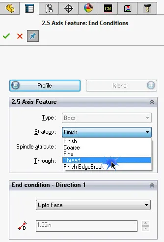
Begin by creating the feature. You can use a Boss, Pocket, or Hole feature. Once you create the feature, you need to select “Thread” from the “Strategy” drop-down menu.
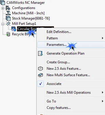
Next, you will need to right-click on your newly created feature and select “Parameters.”
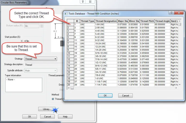
A new window will open and you need to verify that the “Strategy” drop-down menu is set to “Thread.” Click on the “Library” button which will open another window in which you will select the thread type and size then click “ok.” You can now generate the operation.
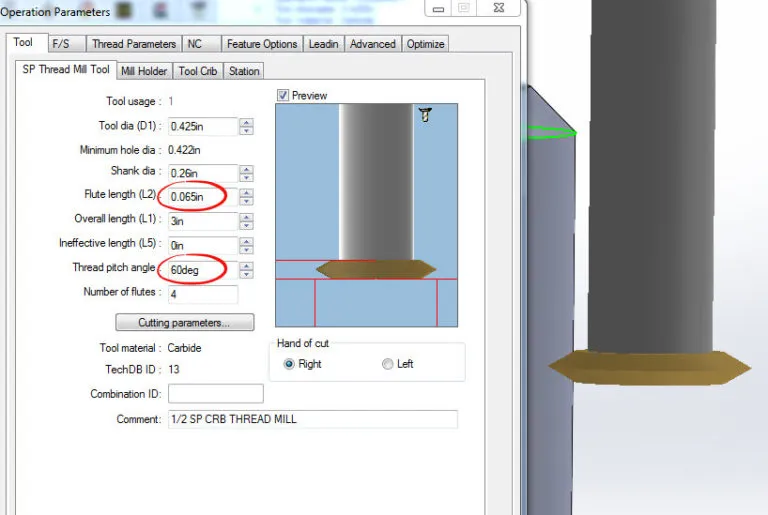
You will need to select the correct tool and verify that the Major and Minor diameter is correct. Start with selecting the correct tool specifications, specifically the “Flute Length” and “Thread pitch angle.” If these are incorrect, the simulation will not look proper.
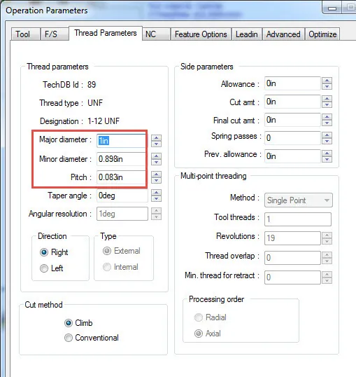
Go to the “Thread Parameters” tab and be sure that the correct Major and Minor diameter is the correct size. The part model must reflect the correct diameter as well because CAMWorks will attempt to choose the correct thread size based on the diameter, and the simulation will not look proper.
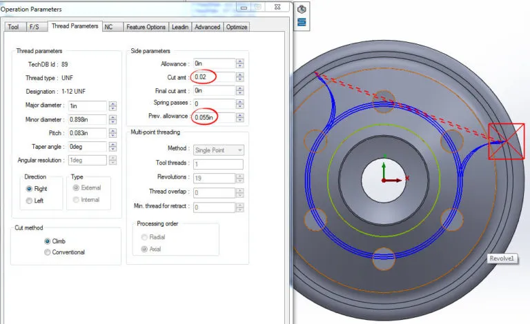
Something to keep in mind is if you want to take multiple passes you will need to add a previous allowance amount. You will specify the amount you want to cut each pass by entering an amount in the “Cut amt” field, and the distance from the final cut that you want the tool to start its first cut by entering an amount in the “Prev. allowance” field. Based on the settings entered in this example, the tool will take a total of three passes at .02” each pass and will start .055” away from the final cut.
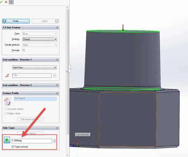
Creating a ThreadMill feature for a tapered thread is almost identical to the process for a straight thread. The only difference is that during the creation of the feature you will specify a tapered amount as shown in the photo below.
Be sure that when you specify the taper amount that it’s tapered in the correct direction using the “taper outward” checkbox. It may or may not need to be selected depending on the direction it is already going but you want the larger diameter at the bottom of the thread.
About GoEngineer
GoEngineer delivers software, technology, and expertise that enable companies to unlock design innovation and deliver better products faster. With more than 40 years of experience and tens of thousands of customers in high tech, medical, machine design, energy and other industries, GoEngineer provides best-in-class design solutions from SOLIDWORKS CAD, Stratasys 3D printing, Creaform & Artec 3D scanning, CAMWorks, PLM, and more
Get our wide array of technical resources delivered right to your inbox.
Unsubscribe at any time.
×
Alert
As of June 2022, Microsoft will no longer support Internet Explorer. To ensure your browsing experience is not interrupted please update to Microsoft Edge.
We Value Your Privacy
We use cookies and similar technologies to analyze site traffic and improve your experience,
and to support advertising and marketing. You can accept all, decline non-essential tracking,
or customize your settings. See our Privacy Policy.