Fortus Tip and Build Sheet Combinations: 3D Printing Tutorials
If you’ve ever wondered what tip and build sheet combinations work best with your Stratasys FDM 3D printers and in what configuration – you’ve come to the right place. Before we dive in, let’s cover the fundamentals.
Tips are labeled as T10, T12, T16, etc., and that means a T10 is a .010” orifice opening producing a .005” layer resolution height of material, and that then correlates to a width of .010” of material creating the “bead” for the extrusion. Here’s a table that breaks down your options.
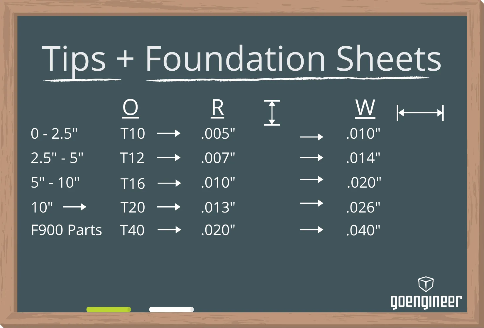
O is for the orifice size of the hole, R is the resolution (the lower the number, the “higher” the resolution, in terms of 3D printing) and W is for the toolpath width.
Note: The dimensions noted on the left column are just are just rough ideas for your part. If your design has smaller features, then a smaller tip orifice would be best to obtain a higher resolution to create a smaller toolpath, which in turn will better fill in the details of your part.
New tips can be used with any material combination that accepts the above-mentioned orifice size. To easily find the tip combinations, for each given material, here’s a quick guide to locate this information in both GrabCAD Print and Insight software.
Finding tip combinations in GrabCAD Print
When you’re in GrabCAD Print, in the bottom right corner, select your 3D Printer under the drop-down menu. In my example below, I selected the Fortus 450mc. On the right-hand sidebar is a set of icons. By selecting the tray settings, the menu drop-down will allow you to see all the materials that are available for that 3D printer. Once you select a material, you’ll then be able to see all of the material slice combinations, with tips, that are available for that material on your selected machine.
(Note: Depending on the system and your specific configuration, all materials may not be accessible with your machine.)
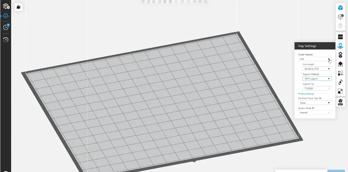
From there, the software also describes the support material combination and the tips that are required to run the support.
Finding tip combinations in Insight
In the Insight Software, on the right-hand side, is the Modeler Setup. In my example, in the bottom right corner, I have again chosen a Fortus 450mc. Users can select a printer, as well as any other applicable information, in the Modeler Setup. By clicking on the machine icon, a new window will open, and this is where you can select the modeler type that pertains to your system. Once that has been selected, you can see the model materials available for that system, the support material combination, as well as the tips/resolution options available for each given material.
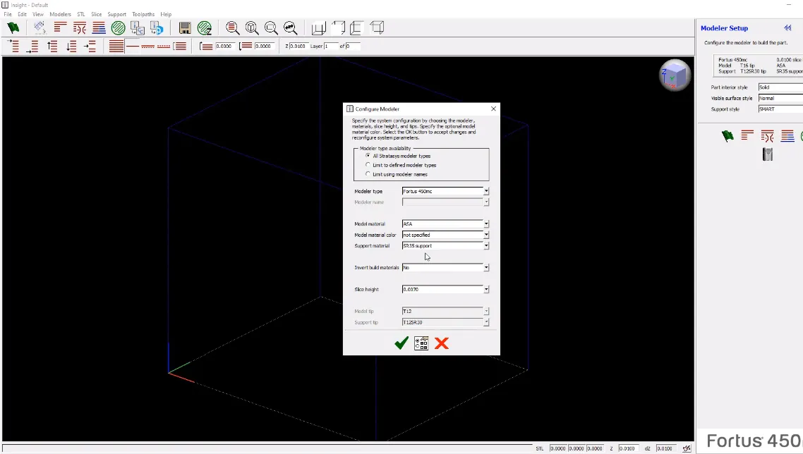
Example: Say you’ve chosen to work with the ASA material at a slice height of .007, this window will show that you need a T12 model tip and a T12SR30 support tip, based on that specific combination.
A tip about tips
When you first receive a T12 or T16 tip, they can be used for any material that accepts that size of tip like ULTEM, Polycarbonate, ASA, and more – fresh tips can be used for any material. But, once you use a tip for a given material, since they are all extruded at different temperatures, that tip must continue to be used for that material for the rest of its life. To clarify, once a material is in a tip, it can be used over and over again but only for that kind of material .
Build sheet combinations
Clear build sheets should be used for ASA, ABS, PC-ABS and PC. This information can be found on the label as shown below.
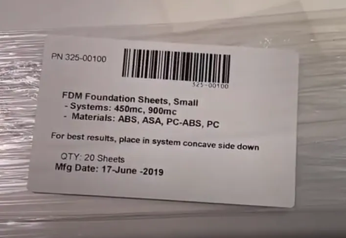
High temp materials like ULTEM and Antero use tan build sheets. You can see an example label below.
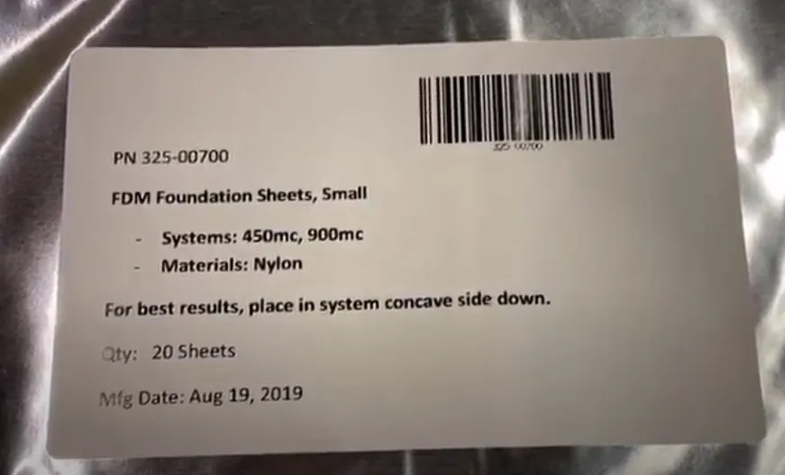
Build sheets that come in the mylar bags are specific for nylon materials. (Having a hard time getting your nylon build sheets to lay flat? This video addresses that.)
I hope this gives you a better idea about what the tip numbers mean, how they correlate to a resolution, and how that resolution translates to a width of material being extruded out. From there, that data then can assist you to understand why, as the part gets bigger, you may want a bigger tip orifice or why when you get into a smaller part, or a part with fine feature details, you may want to drop down to a lower size. Finally, understanding that you do not have to memorize this information but rather where to find it in the software provided by the manufacturer.
For more 3D printing tech tips just like this, be sure to subscribe.

About Michael Brenholt
Michael Brenholt has over 10 years of engineering experience and is currently an Operations Specialist and Stratasys Certified Application Engineer at GoEngineer based out of Atlanta, GA. He graduated from the University of Wisconsin-Stout with a Bachelor's degree in Industrial Technology and a Master’s Degree in Training and Development. Michael is an avid hobby actor, having performed in 22 stage shows, and enjoys the outdoors, hiking 33 waterfalls in a given summer!
Get our wide array of technical resources delivered right to your inbox.
Unsubscribe at any time.