Creating Planetary Gear Assembly mates
In the following pages I will explain the proper way to set up your assembly and mates to create a functional Planetary Gear set that moves as expected.
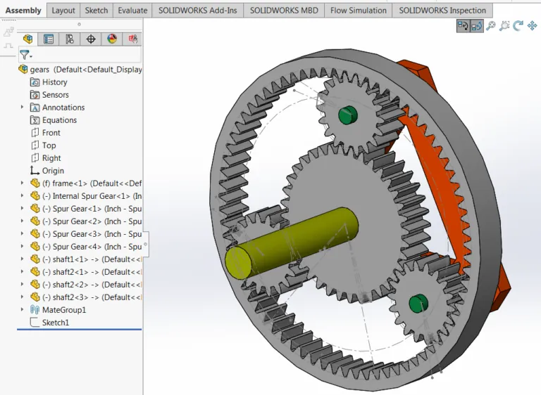
After you insert all components into an assembly and properly constrain them, with the exception of mates that restrict rotation, all of the gears should freely rotate independently but not translate along any axis. In this example assembly, an included “stand” is used to locate all of the components and provide a common reference for mating.
In the above image, all of the components contain 2 relations, a coincident which keeps them all co-planer and a concentric mate to the stand which allows them to rotate. Once these have been created, we can get to the gear mates.
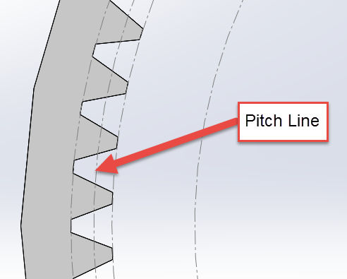
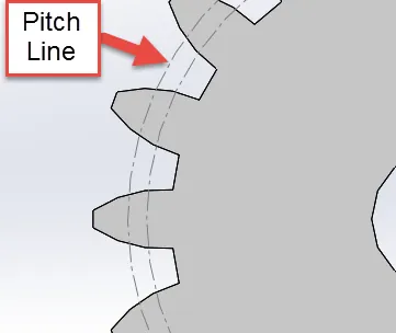
The first step in the process is to have all the pitch lines of the gears defined in a sketch on the part level:
Definition of pitch line:
The line on which the pitch of gear teeth or sprocket teeth is measured and which consists of an ideal line in a toothed gear or rack which bears such a relation to a corresponding line in another gear with which it works that the two lines will have a common velocity (as in rolling contact)
The pitch line, as defined above, is where the gears come in contact with one another. This is controlled by the design of the gear and should come from a reliable data source such as the manufacturer. Once this data has been acquired the best method to use this data is by defining a sketch circle of that diameter.
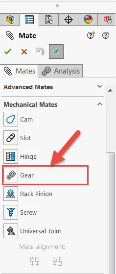
Once these are created, they can be set using the Mechanical Mates section of the Mates feature manager:
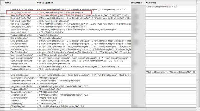
When creating gear mates, the Pitch Line (Diameter) is what you’ll use as your references within the mate. Since this is where the ratio is controlled (where the gears react to each other) it’s very simple to select these sketch diameters for the mating gears. Most of the gears included with SOLIDWORKS come with this information already defined, as seen below. When you use these pre-made gears, they have an incredible amount of equations to define the gear teeth and all incorporated data for correct definition. Put this data to use in your own design. Time savings in this area alone will be monumental. Here is an example of one of the gear file’s equations:
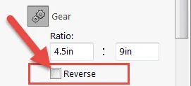
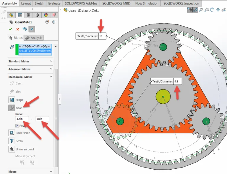
When you have this data available, the gear mates become very simple. As shown below, select the Mechanical Mates sub-menu and select “Gear”. Once that is showing, simply select each of the sketched Pitch Diameter lines of the gears you want to interact. You can see the diameters are pulled into the data screen and also show in the fly-out windows. Test each mate as it is created, being aware of the possibility of needing the mate to be “reversed”. This is a check box found under the defined ratios. The mate basically mates the two diameters rotation to be related by the ratio between them, but it doesn’t know which direction they need to go:
Sometimes, reverse is the correct requirement.
Now do the same for each of the smaller gears to the outside gear and then only one of the small gears to the center gear. Remember to test once each of the relationships is made to verify that they are moving in the correct direction (see “Reverse” issue above). Also, since this is a relationship between the Pitch Diameters of each gear, the software doesn’t notice that there are teeth on each gear. To get the gears to look correct while rotating, prior to creating the mate, rotate the items so they are visibly meshing. This isn’t a requirement for the function of the feature, but it does make the assembly look aesthetically pleasing when everything rotates as expected. Any interference can also be corrected if the mate has already been created. Simply suppress the mate, rotate the gears to the desired location and unsuppress the mate.
Thank you for taking the time to look at this quick tip from GoEngineer!