SOLIDWORKS Drawings Automatic Border Tool
Overview
In the release of SOLIDWORKS 2016, there was an addition to Drawings that allows the designer to modify the border of a default template called the Automatic Border Tool. Using the Automatic Border Tool, you can completely customize the border to allow manufacturers and customers to easily read and interpret your engineering drawing. There are six main categories of a drawing you can customize using the tool:
- Delete exisiting items from the default Sheet Format
- Zone size
- Margins and Borders
- Independent Border
- Zone Formatting
- Margin mask
Launching the Automatic Border Tool
Follow the steps below and you will be able to modify the drawing border of a default template:
- Right-click (RMB) in the center of the drawing and left-click (LMB) Edit Sheet Format as shown below in Figure 1 . This will take you to the Edit mode and show the Automatic Border option.
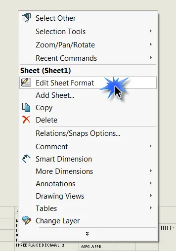
Figure 1: Edit Sheet Format option in the right-click drop down menu
- Right-click (RMB) in the center of the drawing and left-click (LMB) Automatic Border… as shown below in Figure 2 . This will launch the Automatic Border Property Manager.
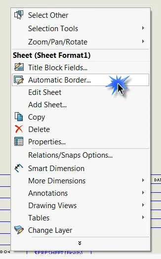
Figure 2: Automatic Border option in the right-click drop down menu
Delete Existing Items from the Default Sheet Format
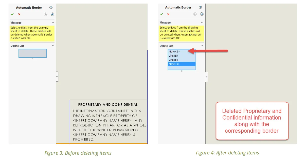
The first page of the Automatic Border Property Manager is to select entities from the drawing sheet to delete. The entities you select to be deleted will be populated in the Delete List.
Figure 3
and
Figure 4
show before and after deleting the Proprietary and Confidential information from the default Title Block. After deleting unnecessary items from the drawing select to
 go to the next page of the Automatic Border Property Manager.
Zone Size
The distribution of the rows and columns can be adjusted in the Zone Size options. Typically, Zone Sizes will be dictated by the drafting standard used in the drawing (ex: ANSI, ISO, DIN, JIS, etc.) These values are well documented in engineering handbooks and online. The Zone Size options are broken up into two sections; Distribution and Region. The Distribution is based on the Region selection. 50mm from center sets the zone size to 50mm and centers the zones to the Margin or Sheet. Evenly sized distributes the Zone Size evenly based on the number Rows and Columns selected. Figure 5 shows the selections for an ANSI Size-A Landsacape Drawing.
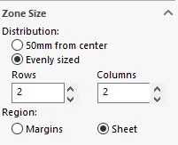
Figure 5: ANSI Size-A Landscape Drawing Sheet Format Zone Size selections
Margins and Borders
The next option you can modify is the Margins and Borders. The Margin of an engineering drawing is the blank space between the edge of the page and the Border. It can be modified using the options boxed in red in Figure 6 .
The Border of an engineering drawing separates the drawing view area from the Margin. The Line Style
 and Border Thickness
 can be modified using the drop-down options boxed in blue in
Figure 6
. Selecting the checkbox next to Double-line border will display two outer border lines.
can be modified using the drop-down options boxed in blue in
Figure 6
. Selecting the checkbox next to Double-line border will display two outer border lines.
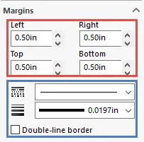
Figure 6: Margins (red box) and Border (blue box) options
Independent Border
Selecting the checkbox next to Independent Border will break the relationship between the Border and Margins. The Left, Right, Top, and Bottom Border options will no longer be grayed out similar to Figure 7 below. You will now be able to modify the Border independently of the Margins. The Border will still maintain a relationship to Zone Sizes.
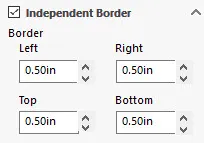
Figure 7: Independent Border option selected
Zone Formatting
Zones in an engineering drawing are helpful to locate specific regions of a drawing when communicating with manufacturers and customers. For example, if there is a Revision in the drawing that needs to be discussed the Zone callout (ex: B2) will easily allow both communicating parties to be looking at the same region of the drawing.
Zone Dividers
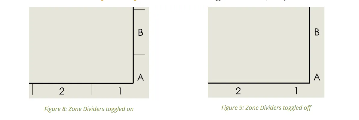
The first option in the Zone Formatting section is Zone Dividers. Zone dividers do exactly what the name entails. They divide the zones of the drawing based on the number of rows and columns selected in the Zone Size section. The Zone Dividers can be toggled on/off by using the check box next to Show zone dividers. Figure 8 and Figure 9 show the Zone Dividers toggled on and off, respectively.
Zone Divider Line Style, Thickness, and Length
The Zone Divider Line Style
and Thickness
can be modified just like the drawing Border. The Line Style of the Zone Divider can be changed to dashed, dot-dash, dash-dot-dot, etc. The Thickness of the Zone Divider can be changed from 0.0071” – 0.0787” or a Custom Size. The Length
 of the Zone Divider can be modified to ensure they work with the Margin settings. Ideally, you would like to easily see the Zone Dividers without having them hanging off of the page.
Figure 10
shows the a close up of the Zone Divider options.
of the Zone Divider can be modified to ensure they work with the Margin settings. Ideally, you would like to easily see the Zone Dividers without having them hanging off of the page.
Figure 10
shows the a close up of the Zone Divider options.
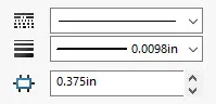
Figure 10: Zone Divider options
Zone Labels and Font
The Zone Labels are the letters and numbers that make up the Zones of the drawing. A1 would be the bottom right Zone shown in
Figure 8
above. In the Zone Labels section, you can toggle on/off the column and rows callouts. You can also modify the Distance
 that the Zone Labels are offset from the Border. The Font of the Zone Labels can also be completely customized. The Font, Font Style, Height, and Effects can all be changed by selecting Font…
 All of the Zone Label options can be seen in
Figure 11
below.
All of the Zone Label options can be seen in
Figure 11
below.
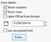
Figure 11: Zone Labels options
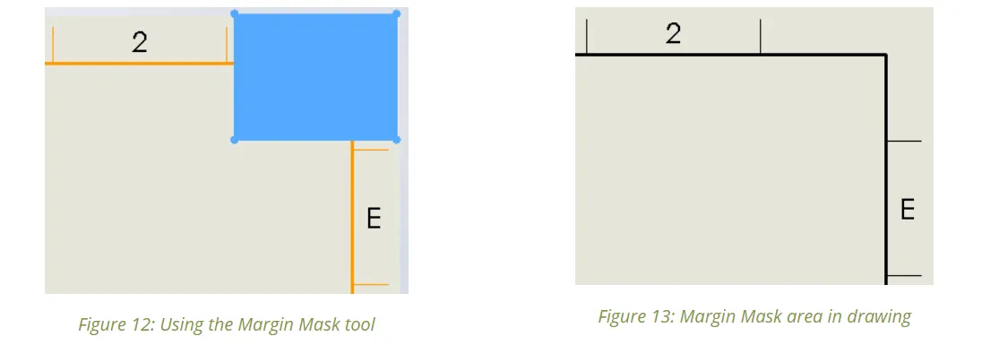
Margin Mask
A Margin Mask is an area of the drawing that hides the Zone Dividers and Zone Labels in the margins. This allows you to reserve a space for notes and assembly instructions within the drawing. To insert a Margin Mask select
Add Margin Mask
.
 You can drag, drop, and resize the Margins Masks.
Figure 11
shows the light-blue area where the Margin Mask area has been placed.
Figure 12
shows the finished drawing sheet template with the Margin Mask inserted.
You can drag, drop, and resize the Margins Masks.
Figure 11
shows the light-blue area where the Margin Mask area has been placed.
Figure 12
shows the finished drawing sheet template with the Margin Mask inserted.
In summary, the Automatic Border Property Manager is a very powerful tool that allows you to customize every aspect of the Sheet Format of a drawing. Now that you have created a custom Sheet Format of a drawing you can save it for future use. To save the Sheet Fortmat, select File -> Save Sheet Format…
![]()
About GoEngineer
GoEngineer delivers software, technology, and expertise that enable companies to unlock design innovation and deliver better products faster. With more than 40 years of experience and tens of thousands of customers in high tech, medical, machine design, energy and other industries, GoEngineer provides best-in-class design solutions from SOLIDWORKS CAD, Stratasys 3D printing, Creaform & Artec 3D scanning, CAMWorks, PLM, and more
Get our wide array of technical resources delivered right to your inbox.
Unsubscribe at any time.