SOLIDWORKS Simulation Composite Analysis capablities
SOLIDWORKS Simulation Premium has the ability to perform a composite analysis. Users can perform a Linear Static, Buckling or Frequency analysis with composite materials.
A composite material is a mixture of two or more materials. This is usually a stiff unidirectional fiber combined with a softer matrix element. The goal of such a mixture is get more desirable overall properties that each individual material could not provide. Composites usually exhibit good strength to weight ratio and is used primarily in the Aerospace and Biomedical applications or sporting goods like tennis rackets.
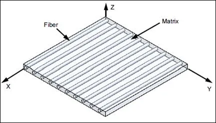
Figure 1: Composite Material
SOLIDWORKS Simulation Premium has the ability to perform a composite analysis. Users can perform a Linear Static, Buckling or Frequency analysis with composite materials.
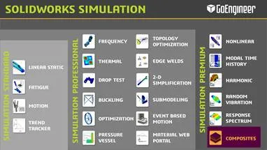
Figure 2: Simulation Product Matrix
The main reason to simulate composites is that the material properties of a composite material is hard to calculate by hand. Just like simulation is intended to decrease the number of iterations needed, a composite analysis tool helps simulate different layer and angle configurations to see which material composition produces stress results that are acceptable.
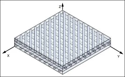
Figure 3 Composite material with fiber angles
There are failure criterias specific to Composites. Tsai-Wu and Tsai Hill are two composite failure criteria commonly used in the industry and these outputs can be seen using SOLIDWORKS Simulation. Finally, the stresses in each layer or the stresses between layers called interlaminar stresses may also be viewed to make critical design decisions.
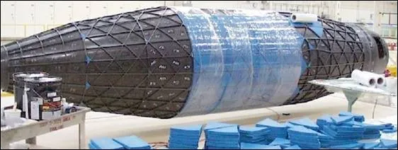
Figure 4: Aircraft built with Carbon Fiber Composite
Let’s look at Composites from a technical perspective. Given the nature of where it is used, Composites are defined using Shell Elements. Hence, each composite part is assumed to have a uniform cross section and a high length to thickness ratio. A maximum of 50 layers may be defined. The type of layups available with SOLIDWORKS Simulation are
SOLIDWORKS provides self-learning Tutorial PDFs and access to self paced Training Files. Once a user has good knowledge of how a Linear Static Analyis and Shell Meshing works, these files should get them up and running with using Composite Analysis as well. SOLIDWORKS also has the ability to export results to other FEA software like Nastran and ANSYS.
Typically for aerospace companies, verification of any FEA tool is critical before they can start using it. SOLIDWORKS has independently verified the accuracy of the composite tools. Click here for links to the verification documentation.
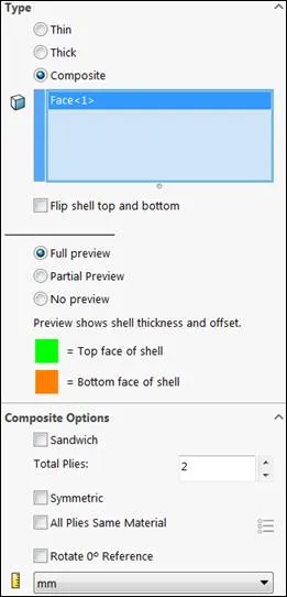
Figure 5: Composite shell definition
![]()
About GoEngineer
GoEngineer delivers software, technology, and expertise that enable companies to unlock design innovation and deliver better products faster. With more than 40 years of experience and tens of thousands of customers in high tech, medical, machine design, energy and other industries, GoEngineer provides best-in-class design solutions from SOLIDWORKS CAD, Stratasys 3D printing, Creaform & Artec 3D scanning, CAMWorks, PLM, and more
Get our wide array of technical resources delivered right to your inbox.
Unsubscribe at any time.