STEP and IGES Files – Avoiding Import Issues
Are your STEP and IGES files imported into SOLIDWORKS acting a little strange?
SOLIDWORKS added the “3D Interconnect” import option to the program in 2017. This allows for proprietary CAD data being opened in its native format, keeping a link to the original part or assembly. Plus, the ability to work seamlessly with third-party CAD files inside SOLIDWORKS. But, for STEP and IGES files, this setting can cause some unwanted results. Below are a few examples of issues you might come up against.
- You can run “Import Diagnostics” on non-native SOLIDWORKS models, but you cannot heal or fix any bad geometry. Modifying (fixing) any of the geometry could change the face and edge identifiers. That, in turn, would break the update capability of “3D Interconnect”.
- Not being able to run “Feature Recognition” on an imported part that was not converted to the SOLIDWORKS file format.
- A STEP or IGES file opened as an assembly in its native format will not allow individual components to be opened in a separate window.
- You can’t float the individual STEP or IGES components in the assembly. This means adding mates will not affect how they interact with one another.
Two Ways to Fix the Issues Above
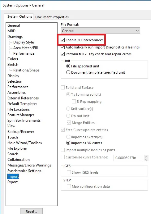
You can turn off “3D Interconnect” by selecting Tools > Options > System Options > Import and clear “Enable 3D Interconnect”. See screen shot below.
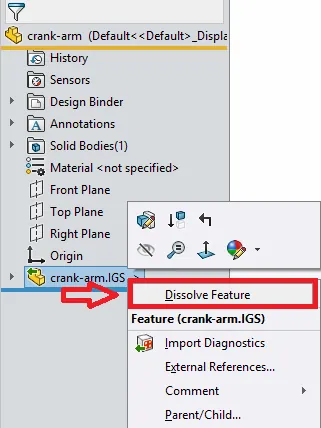
If you don’t want to turn off the 3D Interconnect option, there is a quicker way to change a file to the SOLIDWORKS native file format. In the Feature Manager Design Tree, right-click the inserted third-party native CAD file and click “Dissolve Feature”. See screen shot below.
Note: “Dissolve Feature” is something that can’t be undone. To re-establish the original link, you would have to re-import the file with the “3D Interconnect” option re-enabled.
Some SOLIDWORKS users have also noticed better results with eliminating surface errors in components by importing the assemblies with 3D interconnect and then using “Dissolve Feature”.

About Maurice Cherian
Maurice Cherian is Technical Support Engineer at GoEngineer. He was introduced to CAD while working for the Navy. Maurice has over seventeen years of Software Training and overall CAD experience. He has been using SOLIDWORKS since 2008 and is a certified expert and instructor. He provides SOLIDWORKS training and Tech Support. Maurice is active in the SOLIDWORKS User Group Community in San Diego, presenting and hosting multiple times over the last eleven years.
Get our wide array of technical resources delivered right to your inbox.
Unsubscribe at any time.