STRATASYS – FDM Holes Without Support
FDM. It’s the core technology invented by Stratasys and its’ utility has propelled them to the top position amongst Additive Manufacturing OEM’s. Indulging those who may not know, it stands for Fused Deposition Modeling: a process where thermoplastic materials like ABS, Polycarbonate, Nylon, Ultem and more are extruded through a hot glue gun-like process and deposited to build parts up; one single layer at a time.
Because we can’t suspend material on air during the building process, Stratasys systems are known for their secondary extruders that deposit a sacrificial support scaffold material to provide a bed for overhangs, undercuts, and other floating features with ‘air’ below them.
Why there’s a benefit in elimination?
Due to the nuance of the FDM process and it’s the ability to self-support to a certain degree, both through holes, and blind holes extending in a horizontal direction are prime candidates for support elimination. This is especially true for smaller holes or in situations where hole accuracy/roundness are not critical to the usefulness of the finished part.
Each time we eliminate support from a hole there are 3 distinct benefits:
- Reduced Print Time – The time it takes to deposit the support material is a component of the overall build time. Any support we eliminate ‘saves’ this time.
- Reduced Cost – The support material usually costs the same as the model (by volume). Any support we eliminate reduces the overall cost to print.
- Reduced Post-processing – Support structures are generally removed by dissolving in a detergent solution or mechanically (by hand) using small picks and pry tools. Eliminating support ultimately results in less time spent post-processing it after the build is complete.
Understanding this, of course, begs the question – How do I know if the unsupported hole’s condition is going to be acceptable in the finished part?
The Test Exercise
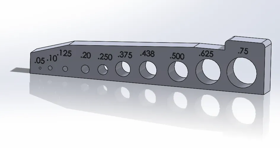
To help answer this question, I designed a test part which is available for download from GrabCAD. This part contains a series of holes with increasing diameters ranging from 0.050 to .750 inches. I have a thin (.063”) and thick (.5”) version to show the effect for the two unique scenarios. My aim is to print and keep these samples without support for future reference when processing files of that or a similar configuration so I know when I can get away with eliminating the supports.
For this exercise, I decided to print and share the results I got printing one of these test parts on a Stratasys F370. It was printed using ASA material, building at a .010 inch layer thickness setting. I mention the specific configuration because the results for one system/material/layer configuration may be different than other configurations. It is probably best to build these for each configuration you wish to analyze in the future.
In order to generate the build files without supports in the holes, you will need to use the Insight® software associated with the F370 printer and the higher end FDM systems like the Fortus 380, 450, and F900. The approach is very easy. Once slicing is complete and supports have been generated, we can simply delete the support curves in the holes, and then resume with toolpath generation as usual.
The Results
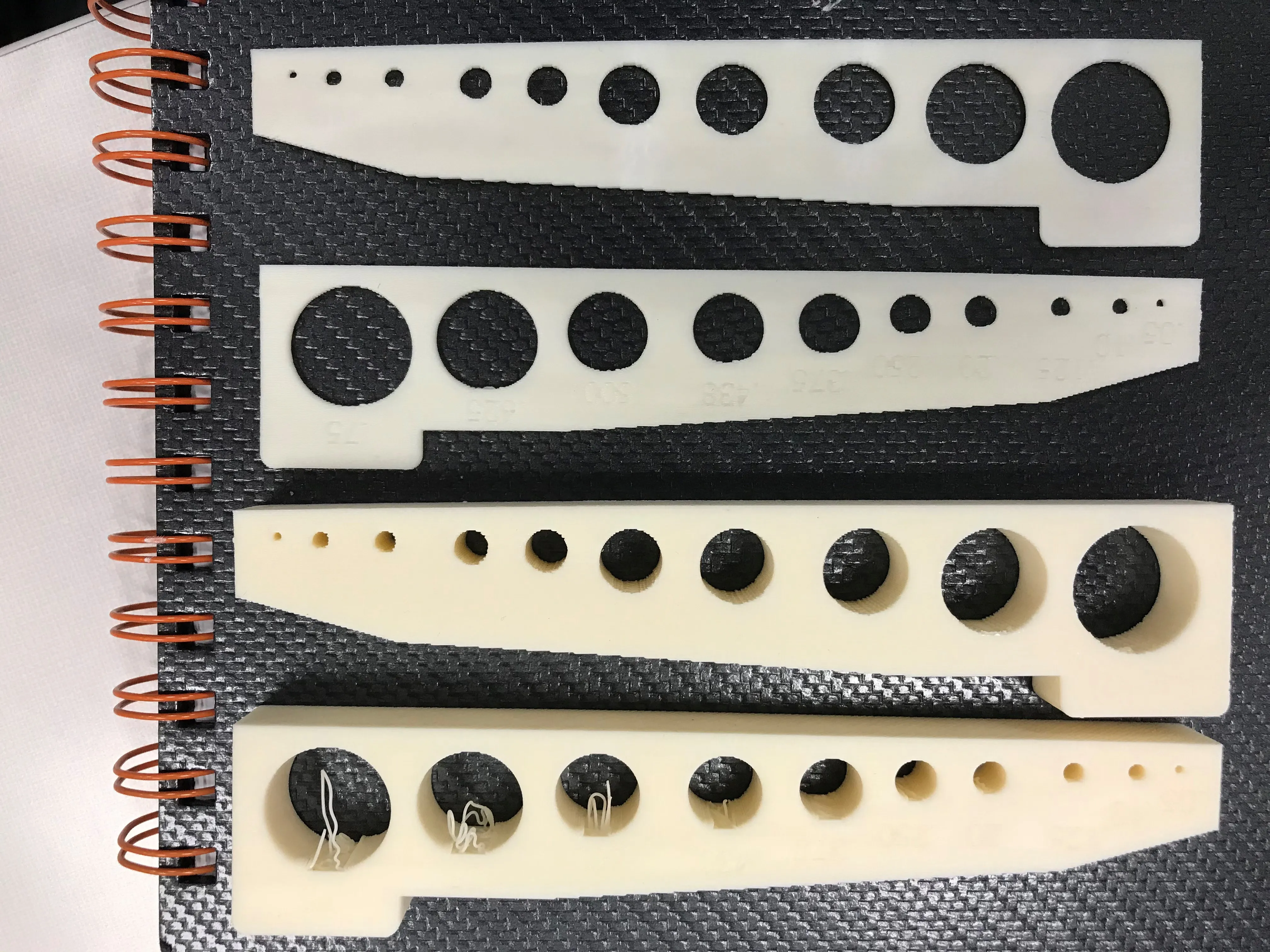
The image shows the result of printing without supports above the corresponding specimen printed using the default support generation methodology. The thick 0.5” test specimen is shown on top and the thinner 0.063” specimen is shown on the bottom.
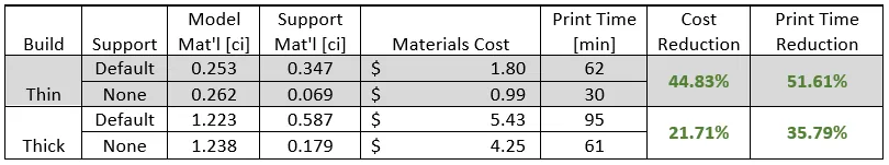
The build estimates for each of the files are captured in the table below. It shows this geometry yielded about 30% savings in cost and 40% reduction in run time overall.
Conclusions
After reviewing the finished models, the result was surprising. Even the biggest holes could be quickly cleaned up with an appropriate sized drill bit or by a quick slice with a hobby knife. It was evident that the thin wall specimen produced a better result than the thicker specimen which I thought was interesting and useful to know. The distilled conclusions regarding hole size are listed below:
- ¼ inch and smaller – Little to no sagging and distortion is visible. Supports not necessary for virtually all applications
- ¼” to ½ inch range – Sagging at the top of the hole is visible but tolerable for most non-aesthetic or low tolerance applications.
- ½ inch and greater – Sagging at the top of the hole is obvious. Will need to be drilled/reamed to restore round appearance. Not ideal when high aesthetic appearance, strength, or accuracy is required.
![]()
About GoEngineer
GoEngineer delivers software, technology, and expertise that enable companies to unlock design innovation and deliver better products faster. With more than 40 years of experience and tens of thousands of customers in high tech, medical, machine design, energy and other industries, GoEngineer provides best-in-class design solutions from SOLIDWORKS CAD, Stratasys 3D printing, Creaform & Artec 3D scanning, CAMWorks, PLM, and more
Get our wide array of technical resources delivered right to your inbox.
Unsubscribe at any time.