SOLIDWORKS PLASTICS
Plastic Melt Flow Simulation Software
What is SOLIDWORKS Plastics?
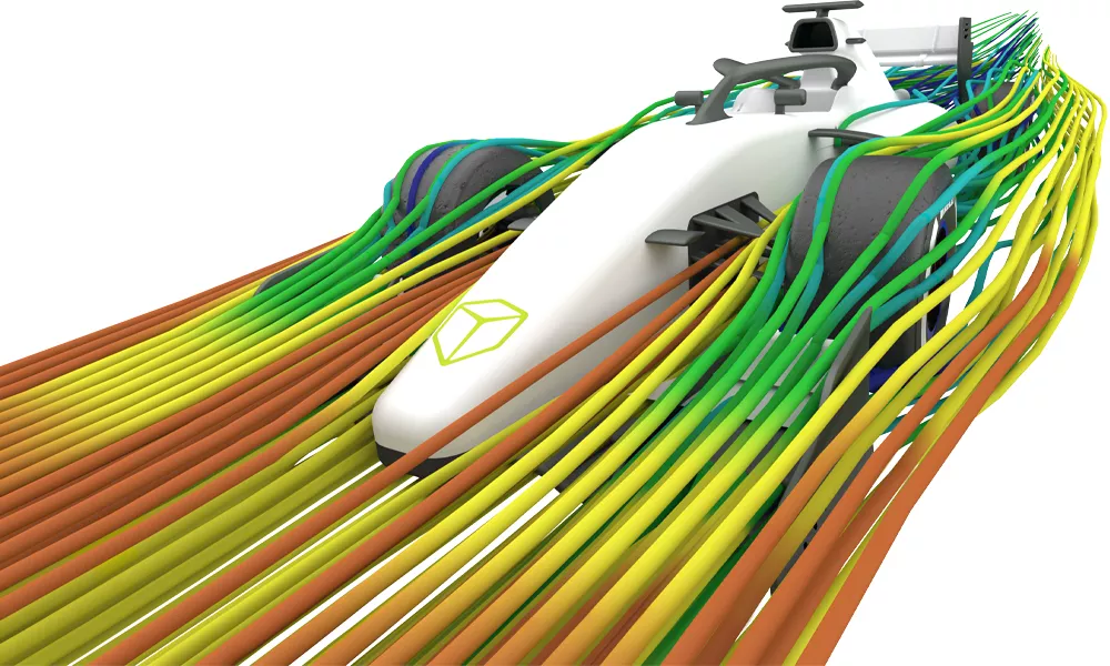
SOLIDWORKS Plastics is the injection molding flow simulation add-in for the SOLIDWORKS CAD package. It simulates the flow of the plastic melt into the mold cavity and provides results that will help part designers, mold designers, and injection molding manufacturers validate and optimize their products. SOLIDWORKS Plastics runs in the SOLIDWORKS interface, which streamlines the workflow to make any design changes on the fly.
Product Design Process
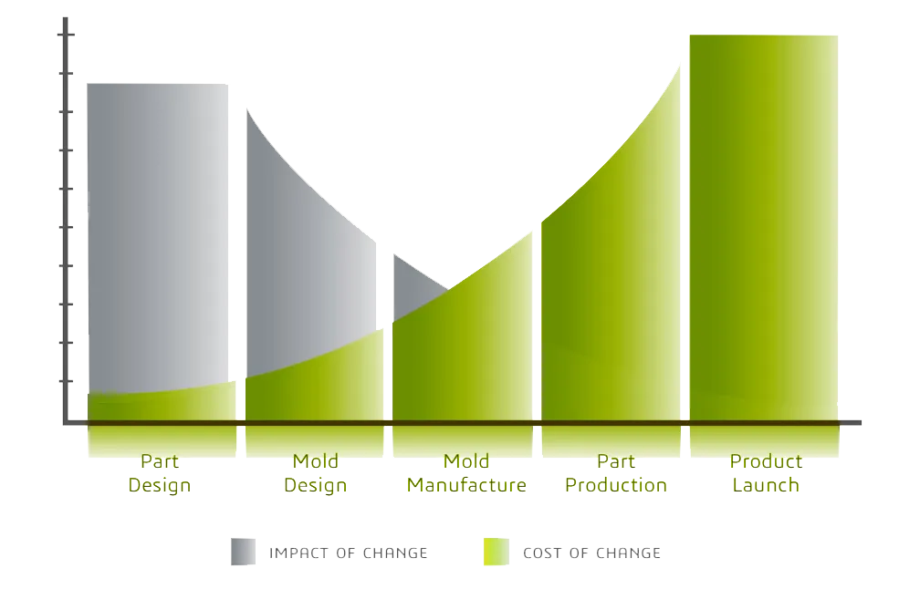
Avoid Costly Mold Cavity Rework
SOLIDWORKS Plastics can drastically reduce the chance of costly mistakes before a Mold Cavity is manufactured. Utilizing the advanced flow simulation tools can help you design efficient products and designs without the large expense of prototype testing. Modifying after a cavity is built not only causes major costs but also extensive labor to rework mold cavities. Let SOLIDWORKS Plastics help you test CAD models before manufacturing begins to ensure the best version of your design will go to production.
"I have successfully used the SOLIDWORKS Plastics software to optimize the design of a part having thin walls and to optimize the cooling lines placement on the injection molding tool. Part warpage was the major issue that I was trying to contain. The supplier conducted a similar analysis using the Moldflow software. I have noted a good correlation in the predicted part warpage between the SOLIDWORKS Plastic and Moldflow."
Wally Szeremeta, Sr. Technologist Mechanical Design 
SOLIDWORKS Plastics Packages
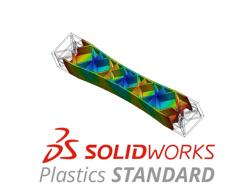
SOLIDWORKS Plastics Standard is the premier mold cavity testing software for part designers. It contains analysis tools to validate and optimize plastic part design for the injection molding process. This is a great tool for a plastic part designer to use to detect potential molding defects before manufacturing begins.

SOLIDWORKS Plastics Professional is the next step up in mold cavity injection testing, with features that assist mold designers and builders to optimize mold design for a consistent processing window. It includes additional tools such as multi-cavity design and runner systems to prevent costly rework by minimizing tooling adjustments.
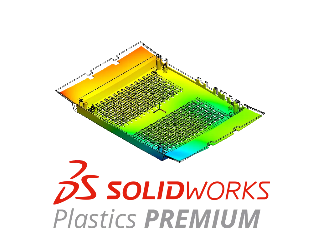
SOLIDWORKS Plastics Premium is the top-level injection molding analysis software tool available on the market. Plastics Premium gives you access to all of the tools that SOLIDWORKS Plastics has to offer. The advanced cooling and warp analysis tools are one of many advanced features used together to get the most accurate shrinkage and warp prediction possible.
Compare Packages
Ease of Use
Design Data Reuse
Materials Database
Meshing
Parallel Computing (Multi-Core)
Filling Phase (1st Stage Injection)
Automatic Gate Location(s)
Instantaneous Fill Time Plot
Sink Mark Analysis
eDrawings Support
Fill Time
Ease of Fill
Results Adviser
Nominal Wall Thickness Adviser
Pressure at End of Fill
Flow Front Temperature
Temperature at End of Fill
Shear Rate
Cooling Time
Weld Lines
Air Traps
Sink Marks
Frozen Layer Fraction at End of Fill
Clamp Force
Cycle Time
Symmetry Analysis
Packing Phase (2nd Stage Injection)
Runner Balancing
Runner Design Wizard
Sprues and Runners
Hot and Cold Runners
Multi-cavity Molds
Family Molds
Mold Inserts
Volumetric Shrinkage
Density at End of Pack
Exports STL, NASTRAN
Export with Mechanical Properties ABAQUS®, ANSYS, DigiMat®
Cooling Lines
Baffles and Bubblers
Conformal Cooling Channels
Runner Domain Category
Sink Mark Profiles
Mold Temperature at Cooling End
Displacement Due to Residual Stress
SOLIDWORKS Services:
Utilize GoEngineer’s Award Winning Support & Training for SOLIDWORKS
Award Winning Technical Support
GoEngineer's extensive SOLIDWORKS technical knowledge and world class support can help you succeed with SOLIDWORKS. Our award-winning team is ready to help you with any task you may have. Using state-of-art remote assistant technology software allows our team to solve most issues within one session. Reach out and see why GoEngineer is the #1 reseller of SOLIDWORKS and Stratasys systems in the world!
- 125+Certified Technical Specialists
- Email, Phone and Chat Support Available
- 98% Exceptional Customer Service Rating
PROFESSIONAL SOLIDWORKS TRAINING
GoEngineer offers online and classroom professional SOLIDWORKS training for organizations and individuals. All our instructors are SOLIDWORKS certified and teach thousands of students each year world wide. The curriculum is very diverse with numerous certified SOLIDWORKS courses to choose from. Each student will receive a Course Completion Certificate and preparation materials for SOLIDWORKS certification.
- Increase Your Earning Potential
- Led by Certified SOLIDWORKS Instructors
- Smaller Classes with Focused Attention
Additional Resources
Take Advantage of GoEngineer’s Extensive Knowledge Base and Resources

Find a Solution
Our robust Knowledge Base contains over 12,000 resources to help answer your product design questions. From basic CAD questions to in-depth guides and tutorials, find your solution here. Find a Solution

PROFESSIONAL TRAINING
Improve your skills with professional training and certifications in SOLIDWORKS, CAM, 3D Printing, and 3D Scanning offered four ways: self-paced, online, on-site, or in-classroom. Certified Training Courses

BLOG
#1 Technical Resource Worldwide - Right at your fingertips. Search or browse through hundreds of SOLIDWORKS tips & tricks, additive manufacturing product developments, announcements, how-to guides, and tutorials. Blog

YouTube Channel
Our YouTube channel hosts hundreds of educational tutorials, product demonstrations, recorded webinars, and best practices for all of our products and services. GoEngineer's YouTube Channel

ONLINE STORE
Order 3D printing materials and consumables, enroll in SOLIDWORKS training classes, and buy official GoEngineer gear directly from our online store. Online Store
WEBINARS
Our engineering webinars are hosted by some of the top experts in the industry. They are always recorded, always free, and always offer a live Q&A. WEBINARS
3D Printing Services
Need to 3D print a part? Our Additive Manufacturing experts will 3D print your part and deliver it to you using the latest technology on one of our professional FDM, PolyJet and SL 3D printers. 3D Printing Services