Why Won't my Wires Route in SOLIDWORKS Electrical - Part 2
Routing wires in SOLIDWORKS Electrical can sometimes be tricky. In this two-part blog series, I’m sharing tips and tricks to make the process easier. In part one we looked at the Wire, Component, and 3D model. In this blog, we’ll discuss the Route itself and all the parameters and parts required for successful functionality. These areas are just as important as the Wire, Component, and 3D Model. Microsoft SQL uses all these areas to collaborate between the environment to make the route.
3D Sketch
One function that SOLIDWORKS Electrical 3D does differently than SOLIDWORKS Routing is a 3D Sketching on the assembly. This sketch is utilized as a pathway for the routes to follow.
One of the keys to this path is that it must be made of lines. There can be no splines at this time. This sketch can be made using the 3D sketch tool in SOLIDWORKS or it can be made using the Create Sketch tool through the SOLIDWORKS Electrical 3D tab.
If you are not well practiced in sketching a 3D model, this can become a bit tricky – but I do have a suggestion! Any 3D modeled part that you will be using in your assembly can have a 3D sketch path created so that you will be able to easily start or connect your models quickly.
Adding a route path to your model can be achieved by following these steps:
- Open your part.
- Create a 3D sketch on your part (it should match the direction that you would like the wire/cable to follow).
- Make sure to convert the sketch to an EWPATH using the Convert Sketch option under the SOLIDWORKS Electrical tab.
- Save and close your part.
Here is what the part should look like once completed.
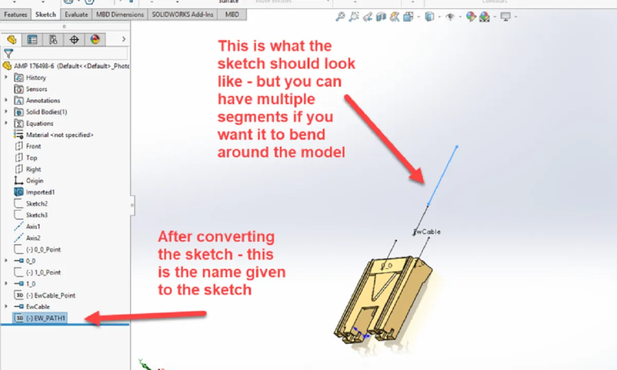
Once the models are placed into your assembly, using the 3D Sketch tool on your assembly, you can then easily pick the endpoints of your model path sketches to connect them.
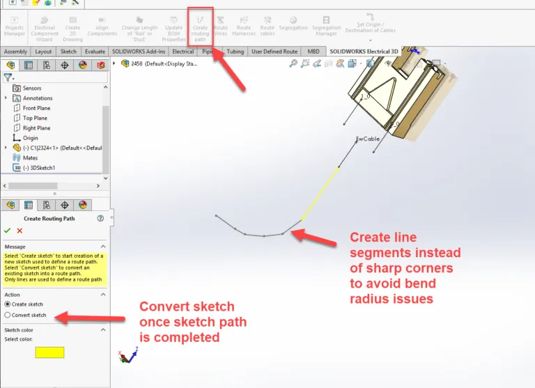
Keep in mind that too sharp of an angle on your sketch will possibly cause an error due to the bend radius of the cable or wire that you will have following this route. Consider making a set of segments to add a slight curve rather than using 90-degree angles to connect your lines.
After you’ve created the 3D sketch on your assembly, make sure you convert it with the SOLIDWORKS Electrical 3D tool. This will then change the naming convention of the sketch into EW_Path. When using SOLIDWORKS Electrical 3D software to route, the assembly needs to have this named sketch to route the wires, harnesses, and cables along a specific profile.
Routing Parameters
The schematics are drawn. The components are placed. The path is set. It is now time to route. For our discussion, we will Route Wires. By selecting the icon in the SOLIDWORKS Electrical 3D tab, the dialog window for the route parameters will appear.
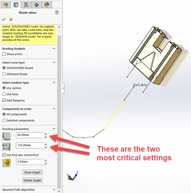
When creating routing paths – you do not need to have all the segments connected, they can be segments that are on the assembly. The first routing parameter is the setting for a route to be able to jump from one segment to another. You may need to measure the distance between segments to find out what this parameter should be.
Selecting the SOLIDWORKS Route will give you a real view, while the 3D Sketch will take a shorter amount of time but will only provide a sketch of your route and not a more realistic view. Also, the 3D Sketch cannot be used for any further documentation.
The second parameter is for the connection points. This setting is the distance from the connection point to a routing path. Only if the distance is equal to or smaller than this setting, will the component be allowed to route. You may need to measure the distance from the connection point to the nearest route to make sure that you will be able to have the route complete. This is one of the main reasons that I like to add a route to the actual component 3D model. This ensures that the distance is less critical.
There is one last thing to keep in mind – this is the bend radius of the wire. If a bend radius is too tight, you may only see a sketch for this area of the route. If you edit the route, you might then be able to adjust the route position, or you might try editing the EW_Path to accommodate the bend radius.
At this point, you should be able to route your wires successfully.
I hope you found this SOLIDWORKS Electrical tutorial helpful. For more SOLIDWORKS tips and tricks please subscribe!

About Cheri Guntzviller
Cheri Guntzviller is a Senior Electrical Specialist with over 35 years’ experience. She earned her Bachelor of Science in Electrical Engineering degree from Lawrence Technological University and joined the VAR channel in 2013 with DASI (now GoEngineer). She is a problem solver and is passionate about teaching and helping others solve problems. Based out of Michigan Cheri enjoys gardening, fishing, construction, and spending time with her family and pets. Cheri is a SOLIDWORKS Certified Electrical Specialist, Trainer, and Professional Presenter.
Get our wide array of technical resources delivered right to your inbox.
Unsubscribe at any time.