Full Metal Iron Man Helmet Project
At the time of this project, I was enrolled in a summer class for my engineering degree, involved in an internship, and working in the technical support group for SOLIDWORKS at GoEngineer. For each, I was required to develop a project. Because my time was stretched in many directions, I was determined to find a project that would cover all three requirements.
My wife is a huge Iron Man fan and I love Marvel. I looked into some objects that I could create in SOLIDWORKS, 3D print with the printers we have here in the GoEngineer office, and then cast in metal for my metals class. After some searching, I decided to go all out and cast a wearable Iron Man helmet in solid aluminum. It was an ambitious task, but it was a project that I knew I could be passionate about as well as satisfy the requirements of all three obligations.
CAD Design in SOLIDWORKS
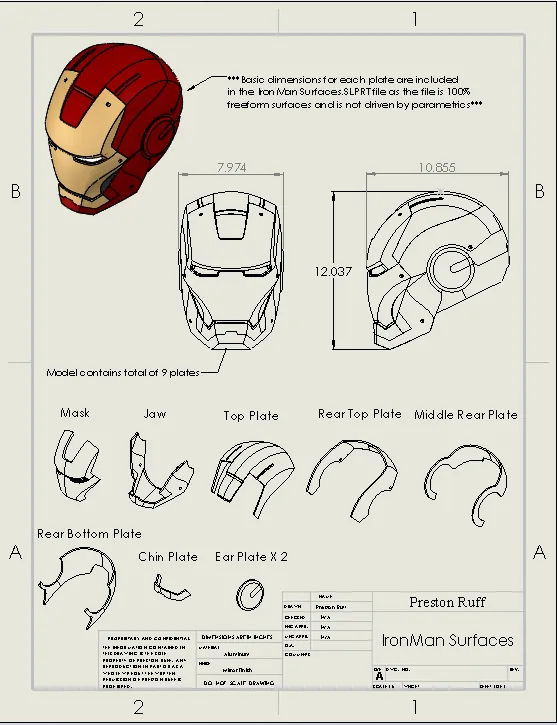
My number one goal in starting this project was accuracy to the movie model. If a part of the helmet looked like a separate metal plate, I was going to make it a separate, independent metal plate. After combing the internet for ideas on how to accomplish this, I stumbled upon a 3D CAD model on the Stratasys-owned GrabCAD website and found the Iron Man Helmet design by Inzamam-Ul-Haq. Of all the models I had previously seen, I was thoroughly impressed with his accuracy and level of detail. He used the Surfacing tools in SOLIDWORKS 2014 to create the file. I decided to use this model as my template.
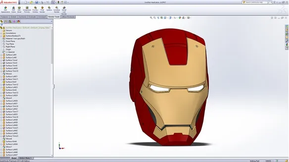
Original file created by Inzamam-UI-Haq
Repairing the surface files
Close Inspection
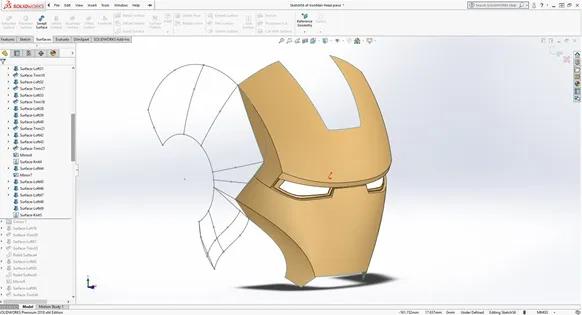
After closer inspection, I found that while the model was accurate, the methodology of the creation of the model was flawed. The entire model was comprised only of surface bodies and many surfaces were created only to look accurate in photo renderings.
Some radii on surface lofts were incredibly small and would not function correctly in subsequent features. It was obvious that he created the helmet for looks, not necessarily to be a functional, usable model. To make the model usable, I had to manually recreate nearly all surfaces or repair them to result in smooth, complete surfaces that could be thickened to a solid.
Because of the flaws and complex geometry, SOLIDWORKS could not automatically thicken the surfaces to a solid, so I was obliged to generate all the surfaces required for thickening on each plate. The result was 9 shelled, solid plates ready for 3D printing. The total time in CAD to repair the model and create solids from all surfaces was about 20 hours. A good portion of that time consisted of learning and applying techniques I had not yet mastered in Surfacing.
Casting Process and Mold Design
After researching methods to cast my parts in solid metal, I settled on the lost-PLA investment casting process. For those who do not know what investment casting is, this infographic by Pennsylvania Precision Cast Parts shows a quick summary of the process. I chose investment casting for three main reasons:
- Investment casting is the best method to capture small features and details
- The surface finish of investment casting is among the best of all casting methods
- Investment casting offers much more flexibility in mold design and orientation
Aluminum was my choice for the casting material because of its lower melting temperature (easier to cast and handle), its lightweight properties (so the helmet would not be too heavy), and its luster. My goal for the final result was to darken the aluminum via anodization and achieve a black chrome finish.
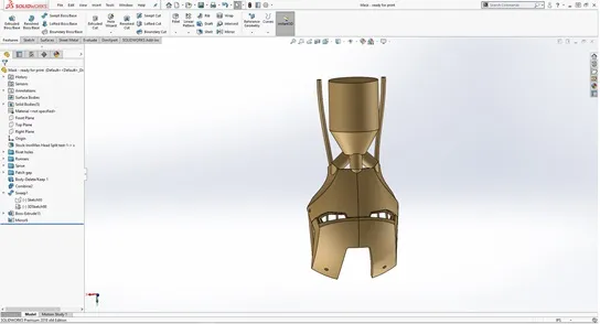
Thickened piece complete with sprue and runners
To get a feel for how the pieces would cast, I watched multiple YouTube videos of DIY hobbyists who performed lost-PLA investment casts in their backyards. The most useful video I found was created by thehomefoundry.
The main takeaways from multiple sources were to include thick runners, plenty of air vents, and a large sprue to increase casting pressure and account for shrinkage. In the mold design for each plate, I made sure to include a large, conical sprue at the top to also act as a riser. I then designed air vents and runners to ensure smooth metal flow into the mold.
3D Printing, Finishing, and Assembly
I decided to print my parts on a MakerBot Replicator (5th gen) mostly because the higher quality Stratasys FDM machines we have here in the office were running around the clock on a large customer order. The quality of the MakerBot prints was questionable, but because all the PLA would be melted out, it sufficed. The shells of each part were thinned to 0.8 mm and the infill on each plate was set to 6-10 percent.
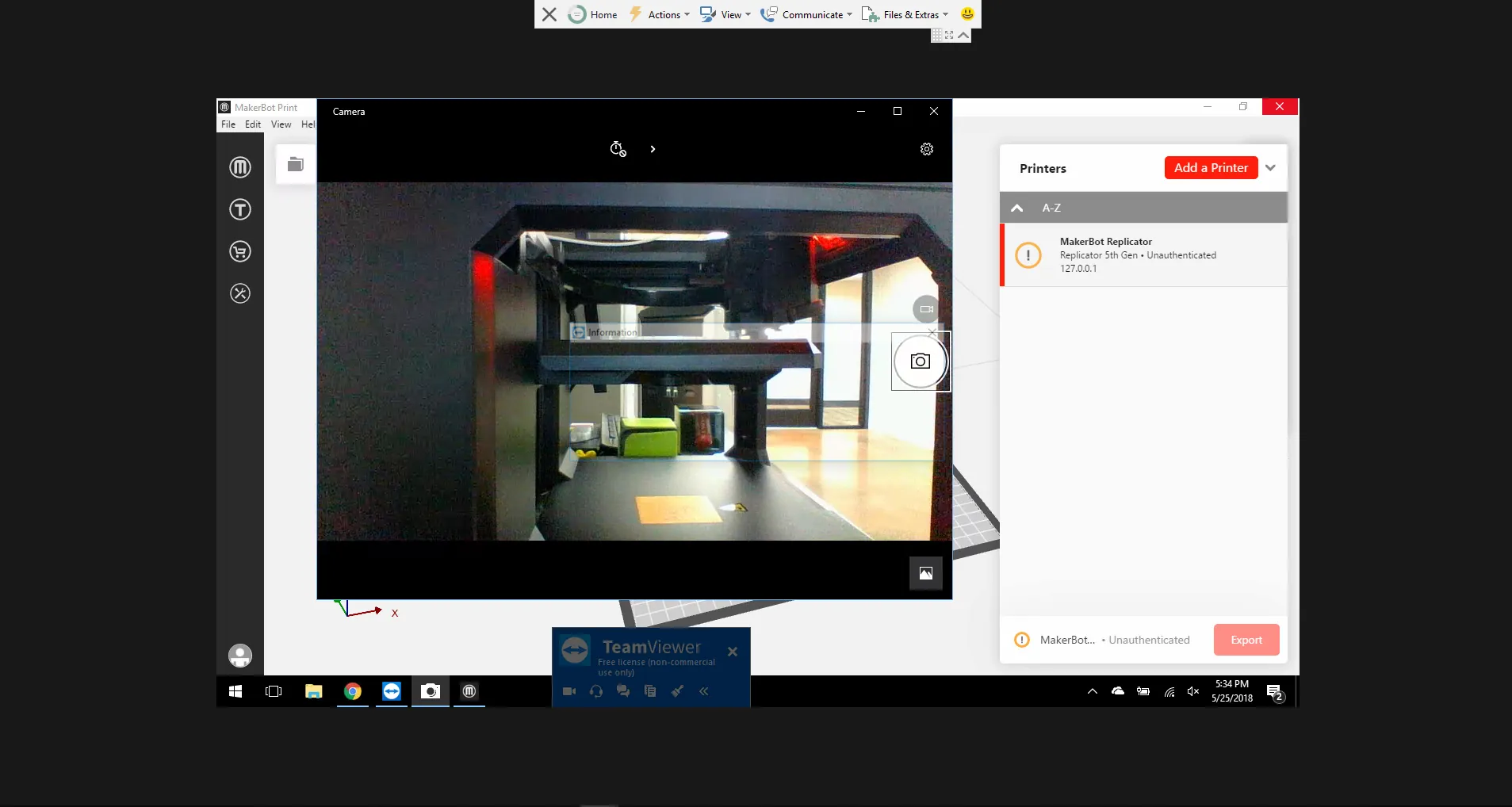
Monitoring the print remotely
To complete all the prints on time, I enlisted the help of my 3D printer (a Creality CR-10). After honing the slicing settings, I was able to produce multiple high-quality prints of the final plates. After burning through about 1.2 kg total of material for all the prints, the plates were ready for finishing and assembly.
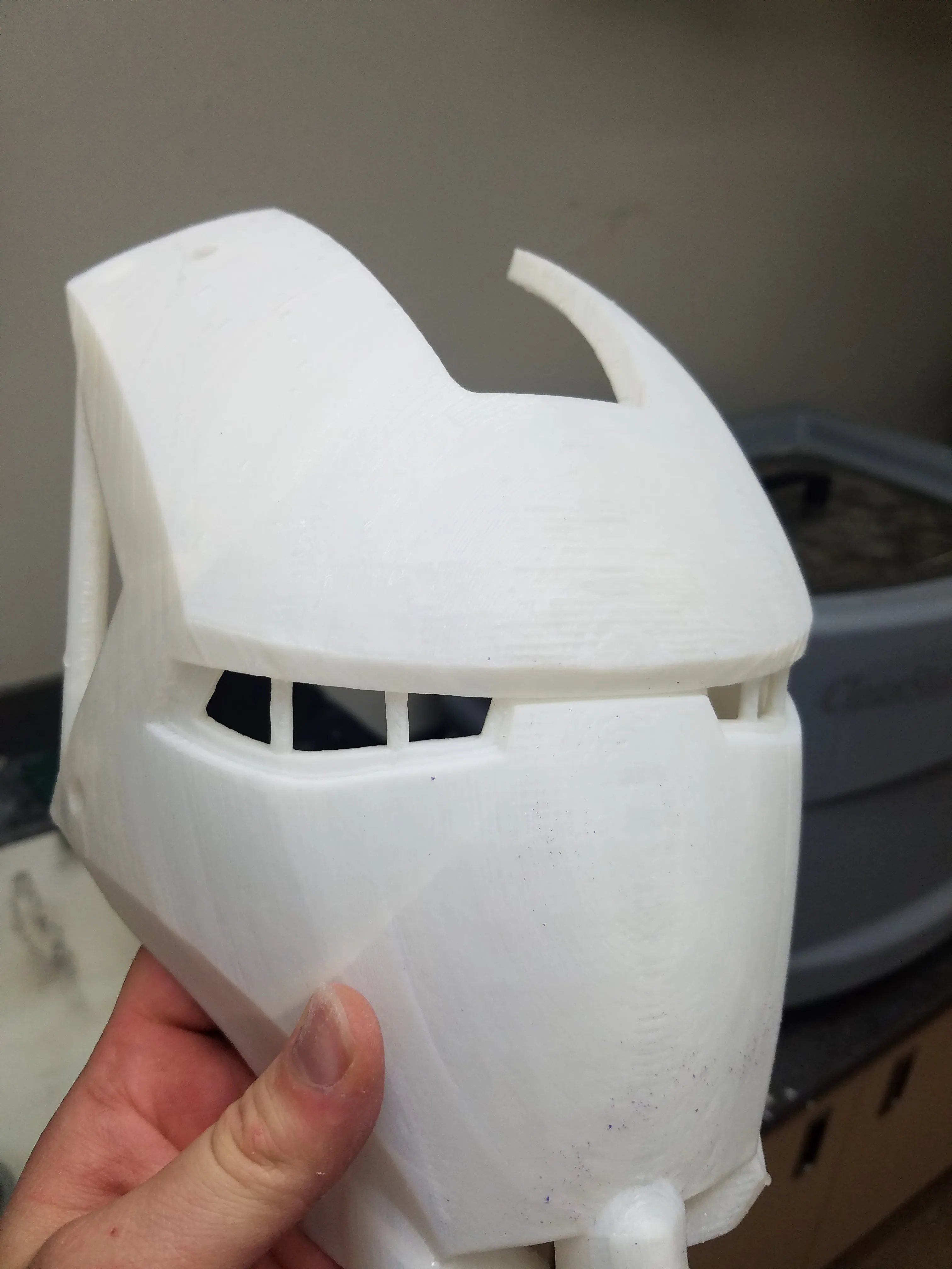
Wet-sanded print
I hand wet-sanded each plate with 120- and then 200-grit sandpaper to achieve a smooth surface on the 3D print. To attach the printed runners and sprue, I used a dot of hot glue and then welded the outside seam with a cheap soldering iron from Home Depot to ensure the slurry would not penetrate the seams. In some plates, I was obliged to melt the surface of the print with the soldering iron due to layer shifts and faulty layers in the 3D prints. The total cost of material used came to about $50 and total printing time around 40 hours.
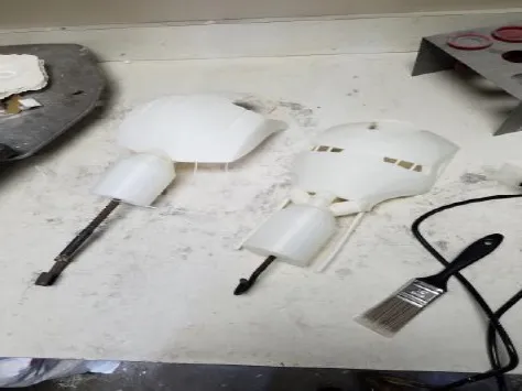
Investment Cast Prep
The next step in preparing for metal casting was the coatings of the trees. Because of the time it took to print each plate and its sprues and runners, the first two pieces were assembled and received their first coats of slurry and zirconium sand before the rest were finished printing. These first two pieces had the lowest surface quality of all the prints. Only after applying three coats did I learn about the trick of rubbing cheap candle wax into the 3D part to produce a smooth surface and minimize post-processing. The rest of the parts received a thorough wax rubbing before applying any coats of slurry or sand.
Painting the first coat
Because of the dry climate of Utah summers, the drying time of each coat of slurry and sand took about four hours. In more humid climates, the drying time can reach up to 12 hours. This is to ensure all moisture escapes the shell mold to avoid cracking when burning out the material.
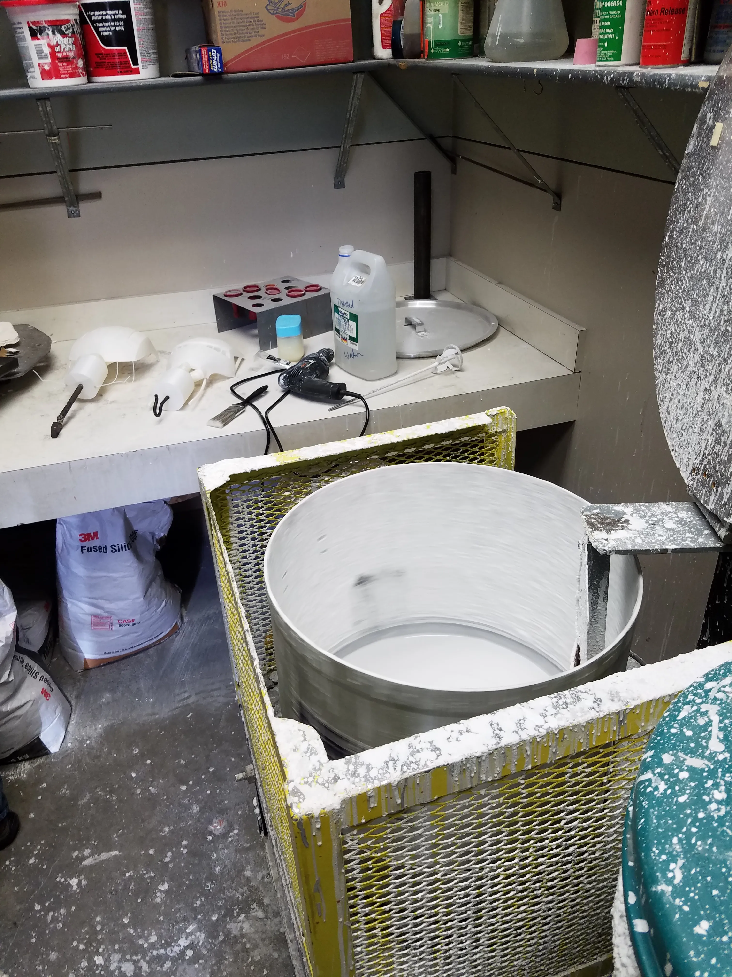
24/7 mixed slurry
Slurry Trick
Another trick I learned from a YouTube video was to apply the first coat of the slurry with an inexpensive paintbrush. This would ensure that the slurry would penetrate small features and fine details. This technique was an impressively successful step in preparing the plates for 3D printing and catching all the detail that I had designed into the plates.
While the prints were being dipped with their successive coats, a friend of mine found a scrap aluminum engine. I used a band saw to cut the engine into pieces and then sandblasted them to remove oil and debris.
This engine was composed of cast aluminum which would significantly increase the quality of my casts due to its silicon content (this acts to improve the flow of the aluminum through the mold). Total time actively applying coats, waiting for coats to dry, and preparing the scrap aluminum was about 50 hours.
Casting
When the molds were ready for casting, I heated a furnace to 800°F for the burnout of the plastic. If the temperature was any lower, the plastic would expand and crack the shell mold. I then placed the molds in the furnace upside-down to allow the melted plastic to flow out. I then increased the temperature to 1100°F for 45 minutes to allow the ceramic shells to fire. This temperature was also chosen because the aluminum would be poured at a temperature of 1300°F.
Having only a 200° difference between the mold and the molten metal would improve the flow through the mold, decrease thermal shock, and minimize the chance of the metal freezing before being able to fill the ends of thin sections. This is a video of me removing the mold from the furnace and my friend pouring the molten aluminum into the mold. You may not see it on the video, but just being that close to the furnace made my gloves and sleeves smoke! That furnace was HOT!
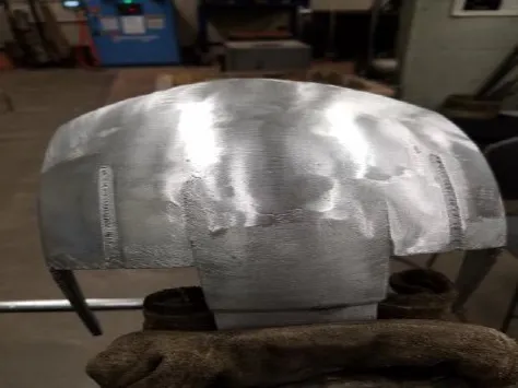
After the metal was allowed to cool, I hammered the shell mold to reveal the cast aluminum plate. The level of detail that was captured by the mold was impressive. Almost all 3D printing lines were visible on the surface of the aluminum. The sprue counteracted shrinkage, the runners I had designed encouraged smooth flow through the mold, and the plastic melted out properly. There were still significant defects in the plates such as inclusions and pinholes, but the overall cast quality was more than satisfactory. The total time actively casting plates came to about four hours.
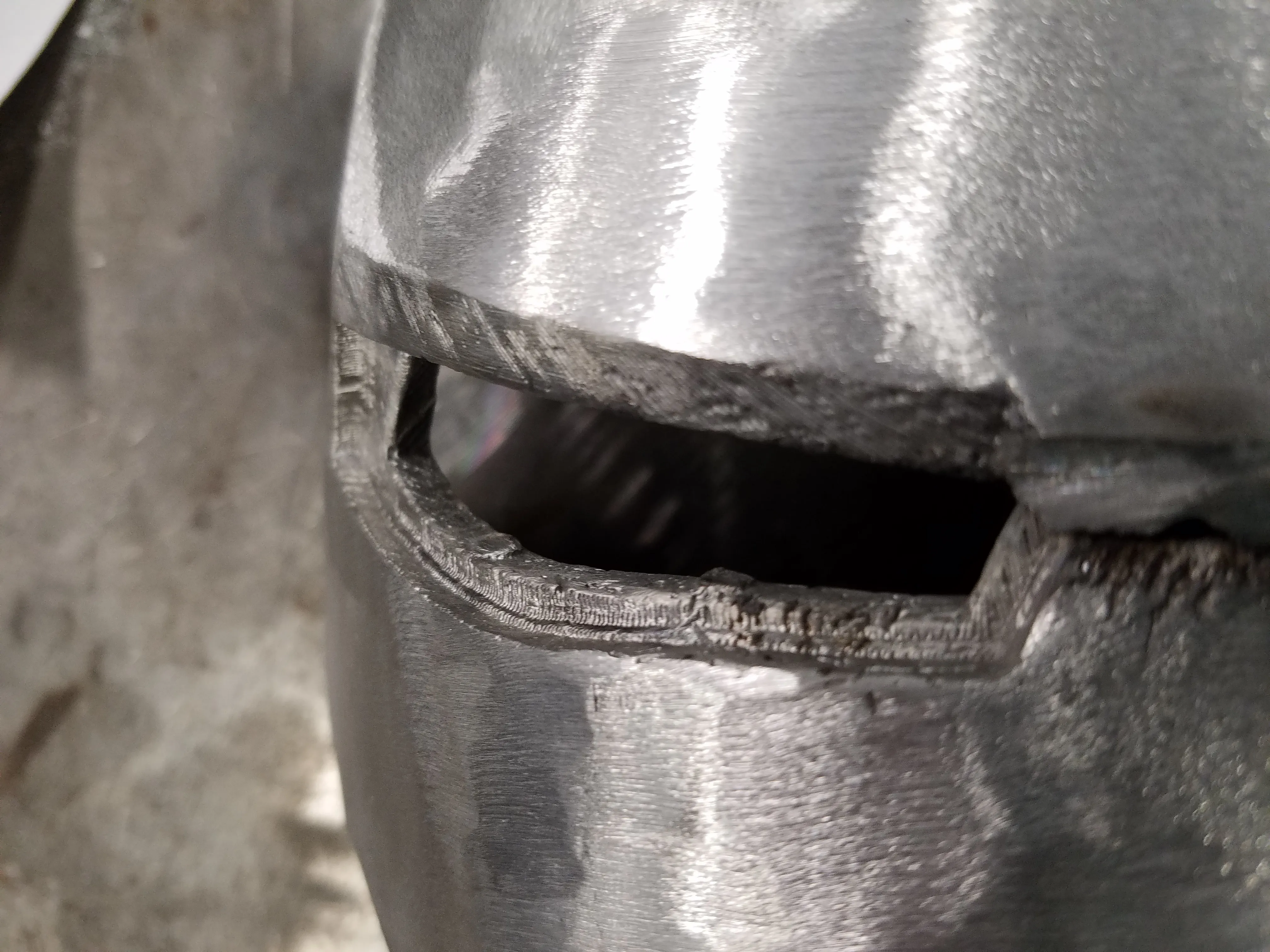
Post-Processing
Because my goal is a smooth, polished surface finish, the defects on the surface of the plates had to be filled with filler metal. I used a TIG (Tungsten Inert Gas) welder to add filler aluminum rod to the trouble spots. After adding filler metal, I took an angle grinder with a flap disc to grind down the weld beads and runner and sprue attachments.
Low-quality print detail
I was not able to rub wax into the first two pieces, so I was also forced to grind down the plate surfaces to remove deep pinholes and print lines. However, because some areas were worse than others, the even curvature of the plates was lost. I will have to go back and regain the curvature by hand, using 80- to 400-grit sandpaper and a buffing wheel. The defects and rough areas in and around the eyes will also have to be smoothed and repaired by a Dremel tool and/or by hand.
After some angle grinding
Broken Chin Plate
One real setback I encountered was in the casting tree that included the three smaller plates (two ears and a small chin plate). While removing the ceramic shell, the small chin plate broke into three small pieces.
To weld the pieces together properly, I attempted to clamp them into the larger jaw plate, but the clamps would not hold the pieces properly or would get in the way of welding. I then had the idea to tape the pieces in the jaw, have a friend hold the pieces, and then weld a bridge.
After each addition of filler metal, I had to spray the weld with a water bottle to cool the piece, blow the water away with an air hose, and then add more filler metal. Just this process took about threehours (mostly due to my lack of experience with a TIG welder).
The total post-processing time for the rest of the plates is TBD as I now only have time to work on the plates in my personal time. However, I have already spent about four hours welding and about five hours grinding and finishing parts.
To Be Continued…
The current state of all plates is unfinished. Multiple plates still have filler metal beads and require grinding and sanding. This is a quick rundown of the remaining steps I hope to complete within the coming months:
- Grind down and sand all plates to reveal final flaws/trouble spots
- Add filler metal with the TIG welder on trouble spots, rough grind down to the surface
- Grind and bend plates to fit flush together
- Finish all parts with 80-, 120-, and 400-grit sandpaper by hand
- Take parts to a local metal shop to be anodized to achieve a black chrome look
- Buff all parts with a buffing wheel to a mirror finish
- Assemble plates together with epoxy pads
- Wire together sheets of electroluminescent sheets behind the eye slots
- Build a display pedestal
- Bask in the glory of a full-metal Iron Man helmet.
A full report with pictures and videos of the final product is already in the works. The bulk of the work has already been completed with printing, coating, casting, and welding. So, the expected finish date will hopefully be some time at the end of July or the beginning of August. Keep your eyes peeled for Part 2 that will include the final finishing steps and final product of the project.
Analysis of Results
I was very pleased with the results of my project and the quality of the final castings. There was not one casting that failed, did not fill correctly, or had major deformations. There were, however, significant inclusions in some areas. I chalked them up to thin printing walls and low infill percentages—settings I deliberately chose in order to minimize print times and costs.
Lessons Learned
The only significant setback I encountered in the raw casting pieces was the breaking of the chin plate while hammering it out of the casting shell. There were also a few things I would have done differently if I were to repeat the project in order to make things easier:
- Reorient the faceplate and top plate to be face up. It would require more 3D printing filament for all the supports underneath, but it would minimize sanding and improve the casting surface finish.
- Reorient some plates in the casting tree to allow easier removal of the sprue and runners and decrease the chance of breaking.
- RUB WAX INTO EVERY PART BEFORE COATING WITH SLURRY. This step would have saved me hours of post-processing time on the first two pieces.
- Only use an angle grinder to smooth out the extra filler metal and welding beads, not grind the curvature of the surfaces. If a power tool is used, the curvature is lost and then requires significant hand sanding to smooth them out again.
- Use files for roughing edges. Fit pieces together, and only remove material as needed. In many cases, I removed too much material with the band saw, die grinder, or angle grinder and had to add it back with the TIG welder.
Lots of Firsts
Every step in completing this project was a first-time exposure for me. So, I learned everything while I was doing it. I had done some surfacing in SOLIDWORKS, but only for a simple personal design. I had never before produced anything in metal, so every step of the investment casting process was new and exciting for me.
After completing this project, I am interested in building my own personal foundry, vacuum chamber, and casting my own parts in metal. I have already learned so much just by watching others on YouTube and their successes and failures. That, combined with my firsthand experience whilst completing this project, I feel I could successfully perform investment casting with my own equipment. While I would most likely not repeat this specific project due to its incredible time investment, I would absolutely venture into other metal casting projects.
Appendix A
SOLIDWORKS Drawing file of the Iron Man Helmet.
About Preston Ruff
Preston Ruff is a Technical Support Engineer and Certified SOLIDWORKS Instructor based out of our Headquarters in Salt Lake City, Utah. He earned a Bachelor’s degree in Manufacturing Engineering Technology from Brigham Young University and is a Certified SOLIDWORKS Expert. For many years, Preston has been passionate about CAD design, 3D printing, additive manufacturing, and being involved with STEM education. He joined the GoEngineer family in 2017.
Get our wide array of technical resources delivered right to your inbox.
Unsubscribe at any time.