Designing a 3D Printed Storage Box Using Multi-Body Part Modelling in SOLIDWORKS
I was recently asked by a colleague of mine here at GoEngineer to help modify a 3D printed box for his friend by improving the lid so that it was more splash proof. In this blog, I highlight several handy techniques for creating and managing changes to an assembly created as a multi-body part in SOLIDWORKS instead of the traditional “bottom-up” method to design the overall assembly.
While it is generally possible to use these features during in-context assembly editing, having them all condensed in a single feature tree made it much easier to work with and edit in the master model.
- Global variables and equations
- Shared sketches and contour selection
- Pattern features
- Split feature
It’s important to consider not only the appropriate context for creating the design, but also think about how changes would be managed later, not at the assembly level, but also at the individual part level. My master model will be the driving parameter for the form, fit, and function of the individual components themselves with any major revisions to the design warranting new individual parts anyway.
Additionally, any individual part features will be limited to aesthetic changes and surface offsets to aid in manufacturability depending on the 3D printer used. I don’t plan on reusing these components in any other future project other than revisions to this one, so having driving features and dimensions unavailable at the part level is not a concern.
Global variables and equations
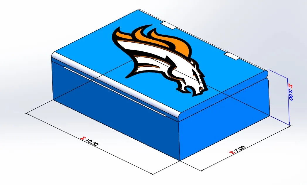
Global variables in this design control the overall length, width, and height of the final assembly as well as the wall thickness used in the Shell feature for both the lid and main compartment of the box.
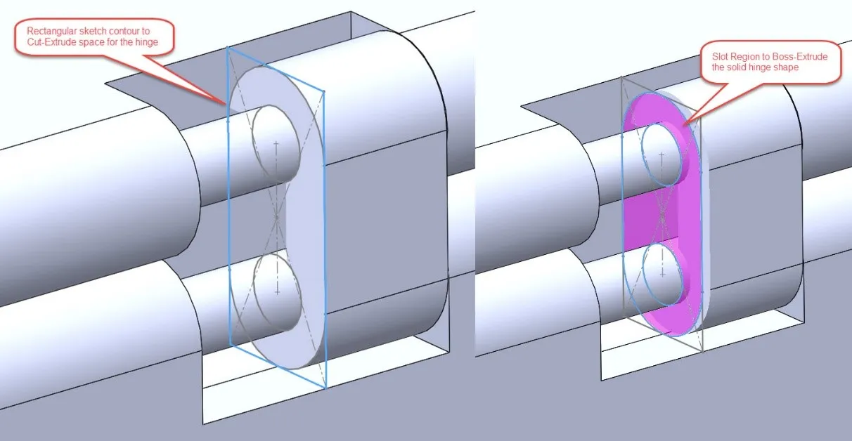
Shared sketches and contour selection
Shared sketches make it easy to create both the cutouts and profiles of split faces and the clip-on hinges in one single sketch. Contour selection allows me to use the larger outer contours as a cut-extrude to generate hinges as well as the smaller inner profiles for the clips themselves.
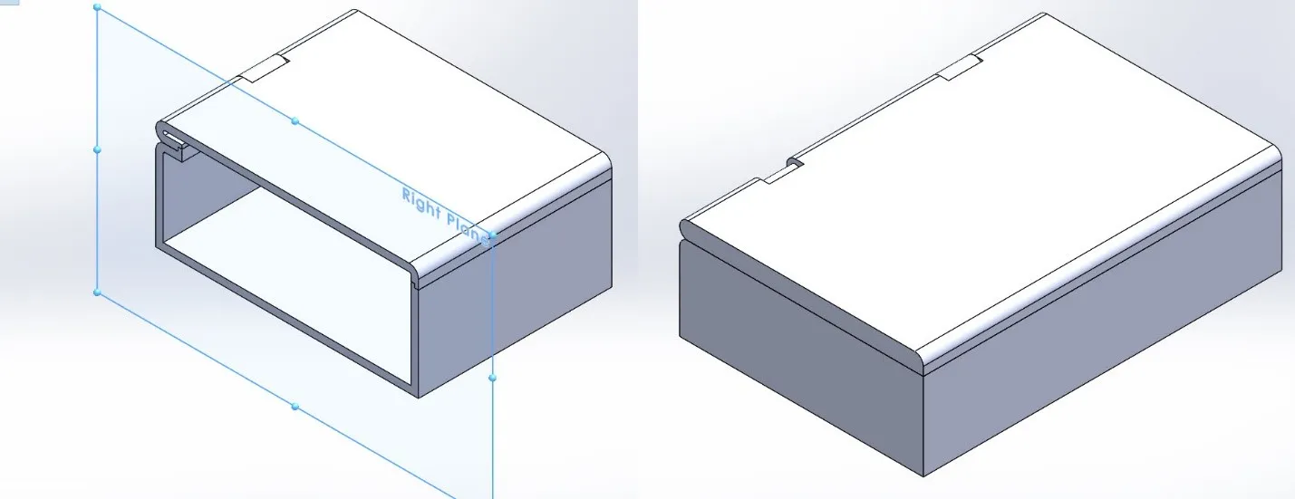
Pattern features
Because I used so many offset dimensions and other equations for my features as opposed to plain numerical values, I ran the risk of feature patterns not rebuilding correctly on the opposite half of my model. To get around this, the Cut with Surface is a feature that can shear away portions of a model with respect to a trimming surface like the Right Plane. Then, using the Mirror Feature on the Bodies to Mirror option, gives me the other half of my assembly with all the critical features already complete without any rebuild issues.
Multi-color printed insert
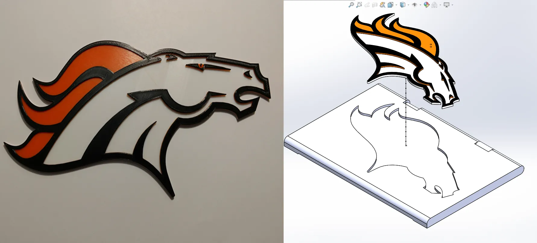
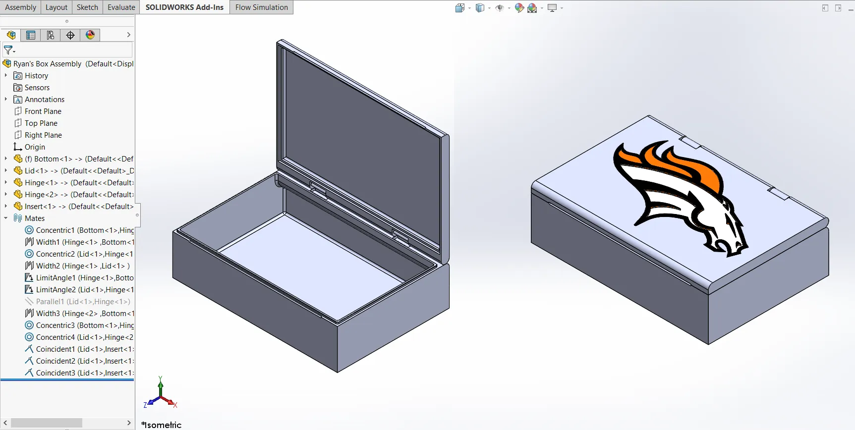
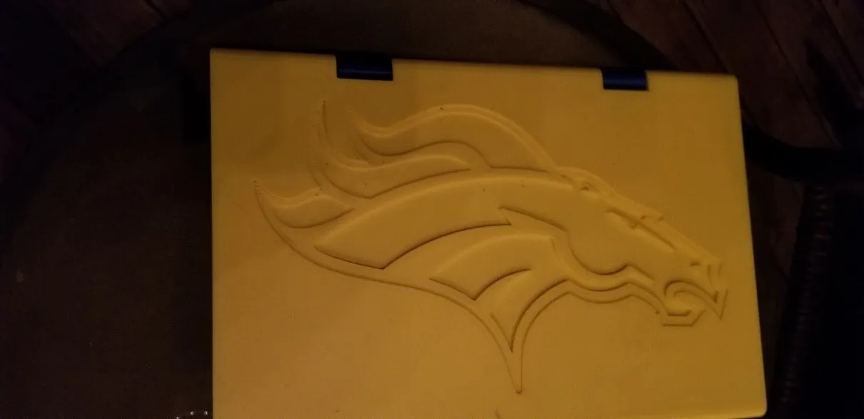
Since the person I’m making this for is a Broncos fan, I wanted to add a bit of flair to make it more personalized. As luck would have it, I found an SVG of their logo that I brought into the free program called Inkscape which allowed me to process it immediately into a DXF that SOLIDWORKS could easily read as sketch entities. I separated the logo out as its own body so I could use my own home printer and some strategically placed filament swaps to make a multi-color part.
Split feature
One of the biggest weaknesses of multi-body parts is their inability to simulate motion like an assembly of those same parts would. I used the Split feature to export each unique body to its own part file. A few Width and Limit Distance mates later, I was in business with a fully moving assembly that I used to check for interference and range of motion.
Making changes to individual parts
As mentioned previously, change management is always an important consideration when constructing a design using these multi-body and master model techniques. The individual parts generated from the bodies have a feature tree all their own and do not propagate any new features back to the parent file. Ryan gave me some design feedback and requested to have the logo cut into the lid directly rather than as an insert. Doing so was extremely easy without having to modify the master model, because I could do it as a part configuration that I could easily switch between the two versions of the design in my assembly.
At the end of the day, using master modelling and multi-body techniques is just another way to add flexibility and ease of control over a SOLIDWORKS design; however it is just as important to identify appropriate situations to use this type of methodology and come up with ways to address those weaknesses if they become a problem in the change management process. This project was a fun way to exercise those skills in a practical way that demonstrated the strengths and weaknesses to the approach.
For more design hacks using SOLIDWORKS and 3D printing be sure to subscribe!

About Miguel de Villa
Miguel de Villa is a SOLIDWORKS Elite Applications Engineer with a B.S. in Mechanical Engineering from the University of California, San Diego. He’s been working at GoEngineer since 2017 helping customers with all their SOLIDWORKS, Simulation and PDM needs. In his free time he enjoys working with his 3D printer, playing video games and building model kits.
Get our wide array of technical resources delivered right to your inbox.
Unsubscribe at any time.