What is a Varied Sketch Pattern?
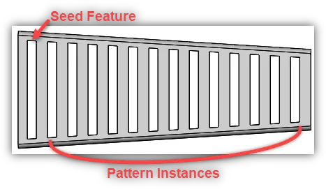
In SOLIDWORKS it is possible to pattern a Feature in such a way that you can create variances in the size of the patterned Instances. This approach is referred to as Vary Sketch (See Figure 1). This method can be obtained using Linear Pattern.
Before we proceed let’s cover some basic pattern terminology in SOLIDWORKS .
- Seed Feature is the feature in which you intend to pattern.
- Instances are the copies of the seed feature made by the pattern.
Figure 1
Why Create a Varied Sketch Pattern?
With the ability to create variances in the size of patterned features, you will save time from having to recreate each feature individually. This would require you to make several similar sketches (slightly different in size) for each feature.
Where to Find Linear Pattern?
Click Linear Pattern  in the Feature Toolbar, or go to Insert-> Pattern/Mirror-> Linear Pattern
How to Create a Varied Sketch Pattern Using Linear Pattern?
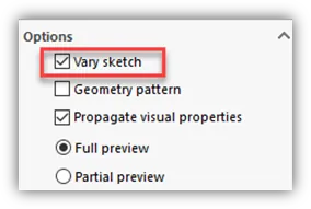
At the bottom of the PropertyManager there is an option called Vary Sketch . (See Figure 2)
- The Vary Sketch option will allow you to create a pattern where the Instances will vary in size depending on the dimensional changes of the pattern’s boundary.
Vary Sketch Pattern – Creating the Seed Feature
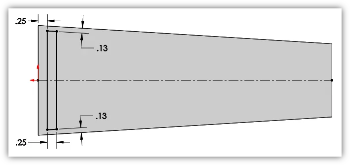
Before we create a Vary Sketch Pattern, we must first discuss how to create the Seed Feature. Since the pattern will vary according to the model boundaries, we must constrain the dimensions of the Seed Feature sketch to those same boundaries. In the example above (See Figure 1) we have a Sheet Metal part that has an Extruded Cut as the Seed Feature. Let’s take a look at the sketch for the Extruded Cut (See Figure 3).
Figure 3
Notice how the sketch lines towards the top and bottom are parallel to the angled edges of the face (or sketch plane), and how the dimensions are placed. To use the Vary Sketch option you must have a Seed Feature with no overall length dimension. This dimension would need to change as it is patterned, so keep sketch dimensions to the boundaries of the sketch face. There is an overall width dimension, but this will not change as it is patterned.
Using the Vary Sketch Option
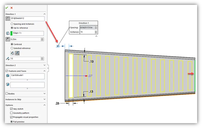
After the Seed Feature is created, highlight the feature in the Feature Manager Design Tree and click Linear Pattern. For Direction 1 we will choose the horizontal location dimension instead of a reference edge (See Figure 4).
NOTE: A dimension must be chosen here to use the Vary Sketch option. If an edge is chosen Vary Sketch will be grayed out.
Figure 4
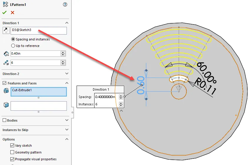
For this example, we have 15 Instances, but we want them to stop a 1/4″ from the end of the part. To do this I have chosen the Up to reference option under Direction 1 and selected the reference edge (highlighted in green) at the end of the part. I have typed in the value for the Offset and selected Centroid for reference. Under Options click Vary Sketch, then click OK. (Please refer to the SOLIDWORKS help menu for a full run down of the Linear Pattern PropertyManager).
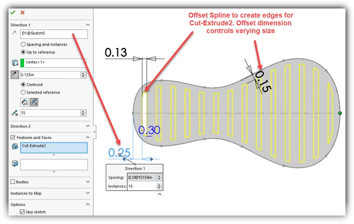
More Examples of a Varied Sketch Patterns
Here are some more examples using the Vary Sketch option (See Figures 5 & 6). I hope this article has been informative to you and thank you visiting the GoEngineer blog!