How to Handle a Vortex Across a Pressure Boundary in SOLIDWORKS Flow Simulation
This article addresses why SOLIDWORKS Flow Simulation will give a warning while solving stating that there is a vortex occurring across a pressure boundary as well as methods of how to accommodate for this to remove the warning.
What is a “Vortex Across a Pressure Boundary”?
In SOLIDWORKS Flow Simulation. a vortex is a region in the fluid domain which causes a swirl in a region where there is asymmetric drag in the flow field. The vortex itself is an expected phenomenon which itself is not problematic. When that vortex is allowed to generate across a theoretical boundary within a CFD analysis that can cause the results to deviate from reality in the immediate vicinity of the boundary or also cause the solver to fail to produce results at all. For that reason, it is important to note where this is happening in analysis and take steps to avoid it.
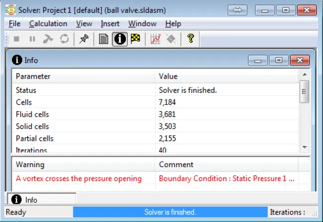
Figure 1: The Flow Simulation solver will show this warning when a vortex is occurring across a pressure boundary.
How can this be fixed?
The vortex itself is generating because of the local solid geometry near the pressure boundary of a CFD setup. If the flow through the boundary is not symmetric a low-pressure region can generate in front of the boundary and allow fluid to pass the wrong direction through the boundary as intended. The fix for this is to “build-out” the model geometry. This means that the solid model needs to have more of the real-life geometry added to the setup so the flow field can be allowed to have the vortex and then transition into a unidirectional flow.
Solution 1: Add Geometry
An example of a vortex across a boundary would be directly from the first Flow Simulation tutorial in SOLIDWORKS (these tutorials can be found under ‘Help’, ‘SOLIDWORKS Simulation’, ‘Flow Simulation Online Tutorial’ once the Flow Simulation add-in is turned on). The ball valve, as it is set up in the tutorial, has two lids that are positioned close to the ball of the valve. In situations where the ball valve is not set completely open the flow through the valve is forced to be asymmetric as it passes through the pressure outlet.
The asymmetric flow out the pressure boundary allows fluid to backflow through the theoretical pressure boundary and creates the vortex that is seen in Figure 2.
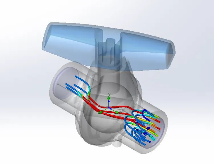
Figure 2: Asymmetric flow through a ball valve shows a vortex occurring on the pressure outlet boundary.
Since the issue only exists on the outlet side of the model that is the only side that needs to be “built out”. In this example, a straight pipe is placed off the end of the valve extending the fluid region and moving the pressure boundary further away. In this way, the flow can have a vortex and then be allowed to transition into the unidirectional flow as it might in real life. Figure 3 below shows that the vortex downstream from the valve remains but is now allowed to fully form before leaving the fluid domain.
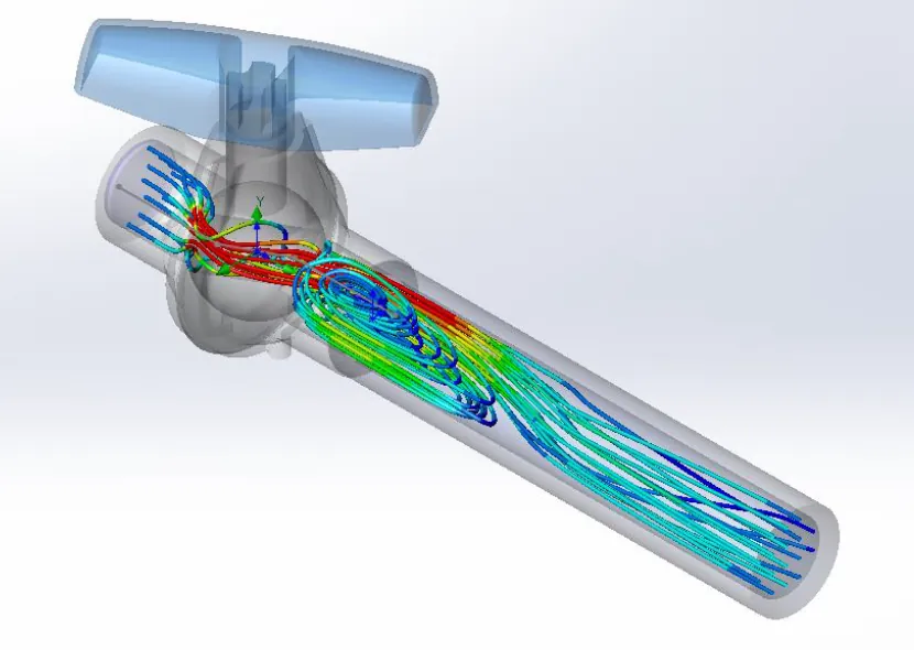
Figure 3: A straight pipe added to the end of the ball valve shows how the pressure boundary can be moved away from the vortex that is being formed.
Solution 2: Release to Pseudo-External Environment
Solution 1 is possible when it is reasonable to assume there is more piping after the valve that can be put into place. This is not always true. Solution 2 examines how to handle the valve’s behavior when releasing it into a larger reservoir. An entire tank could be modeled to resolve this vortex across boundary warning or this could be modeled as an external analysis but that would make the Flow Project take prohibitively long to solve if the valve is the only thing being analyzed. In this case, it may be suitable to model only a portion of the tank where fluid plume flows into. This setup is shown in Figure 4.
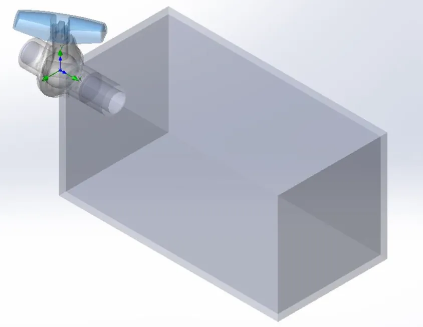
Figure 4: A small modeled enclosure attached to the ball valve.
Only part of the tank is modeled so on 5 of the 6 internal surfaces a pressure boundary is defined that will represent the undefined fluid volume in the rest of the tank. The face immediately adjacent to the valve is not applied with pressure so as to represent the tank wall. The result is that the fluid plume generates in the now open region beyond the valve allowing, again, for the vortex as the valve to generate and then dissipate as shown in Figure 5. In this case, however, a warning for vortex crossing the pressure boundary will still likely generate but will impact the results at locations away from the valve exit and the fluid plume.
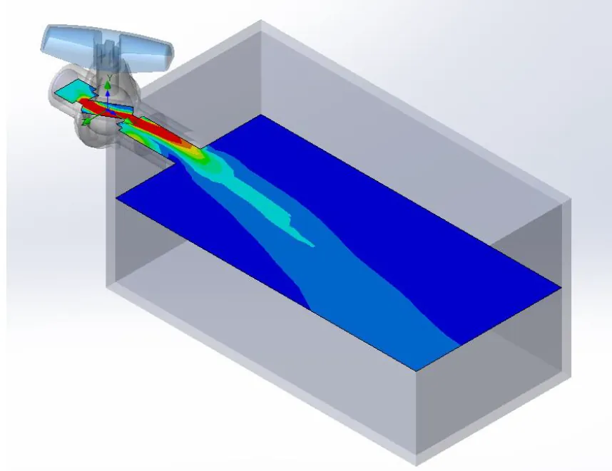
Figure 5: The fluid plume generates in the pseudo-external environment created attached to the valve.
Conclusion
Where possible create a solid model where a vortex will not cross a pressure boundary or move the pressure boundary itself away from the region of interest in the fluid domain.

About Ryan Dark
Ryan has been in the GoEngineer technical support team since February 2008 where he most notably provides support for all FEA and CFD software offered by SolidWorks. His most recent accolade is the title of Elite Application Engineer awarded by SolidWorks Corp.
Get our wide array of technical resources delivered right to your inbox.
Unsubscribe at any time.