Kinetic Art Project: Modeling the Fin - Part IV
Thank you for returning to my Kinetic art project series. Today’s blog is focused on modeling the fins. If you missed my previous post, you can read that here: Kinetic Art Project: Worm Gear.
I wanted to push the print volume boundaries of our Stratasys Fortus 250mc, which is 10”x10”x12.”
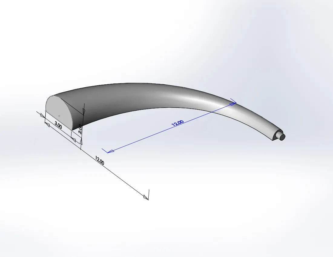
Figure 1 – The Loft
The general shape is pretty simple. It is a cylindrical extrusion and a loft. The cylinder will be how we attach to the hub. The loft was a 90° angle and 12” in the X and Y directions (see Figure 1). I needed to trim the wide end such that it will be inscribed within a 36” circle. The trick here is to create some construction geometry to locate where the center of the hub would be (see Figure 2).
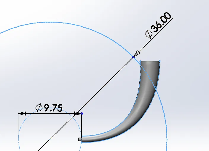
Figure 2 – The Cut
Lastly, I mirrored the fin to create an opposite hand version. To make it easier to switch between the different versions, I created a different configuration for each hand to make it easier to use in the assembly.
Finding and fixing issues
When initially planning this portion of the project, I identified an opportunity to make a mold and cast the fins. Casting will be beneficial because of the large number of identical parts. With this in mind, I did a Draft Analysis of the part and realized I need to modify the profiles of the loft to remove the undercut (see Figure 3).
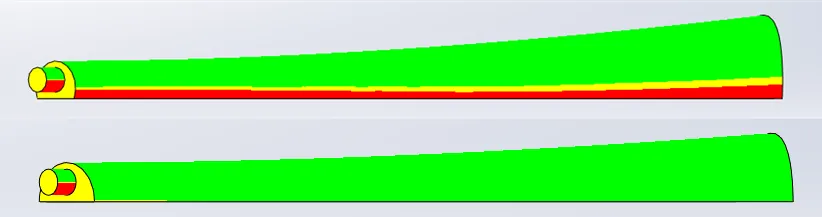
Figure 3 – Draft Analysis before and after
Later, I added the fins to the assembly which you can see in Figure 4, and this became a problem: I realized the two layers would be crashing into each other. I went in and again modified the profile for the loft to keep the overall thickness of the part uniform, thereby reducing materials, and keeping them from colliding.
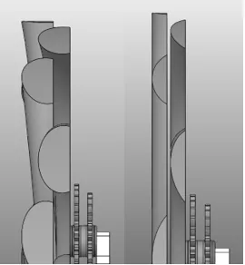
Figure 4 – Side view of the assembly showing before and after
The last hurdle with modeling the fins is getting this to correctly 3D print. I was using a Stratasys Fortus 250mc with a build envelope of 10”x10”x12”, yet the bounding box for the fin is 15.2”x5.5”x1” so, in order to print, I had to orient the fin to go from corner to corner. I was able to print both orientations of the fin in one print.
Stay tuned; the next article will go over the fiasco of making the mold of the fin.
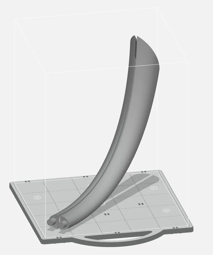
Figure 5 – Preparing for print

About Brandon Harris
Brandon is a BYU-Idaho graduate with a Bachelor’s Degree in Mechanical Engineering. He is an avid tinkerer, and consummate rapid prototype hobbyist with prior experience designing for the Architectural/Construction industry. Brandon is part of the technical support team for GoEngineer serving as a PDM specialist since August 2018.
Get our wide array of technical resources delivered right to your inbox.
Unsubscribe at any time.