Kinetic Art Project: Creating a Worm Gear - Part III
Thank you for returning to my Kinetic art project series. Today’s blog article is focused on creating a worm gear. If you missed Part 1 and 2, you will find the links at the bottom of this post.
I decided to use a worm gear since I needed to have the motor perpendicular to the gearing to help minimize the profile of this project. That presented an opportunity to apply some unique solutions.
The benefit of the worm gear is it allows me to convert the motion from the motor to the gears in a compact way, with an added benefit is that it looks fantastic. Since SOLIDWORKS Toolbox does not contain any worm gears, I needed to create my own.
Study
There are many styles and methods to create worm gears; I will elaborate on three. The first can be simplified down to two cylinders perpendicular to each other as seen in Figure 1, DETAIL A. The second is to have a worm wheel as shown in Figure 1, DETAIL B; in this case, the receiving gear has a concave outer ring in order to increase surface contact. Finally, Figure 1, DETAIL C uses a worm wheel and a hyperbolic worm gear which provides the greatest amount of surface area.
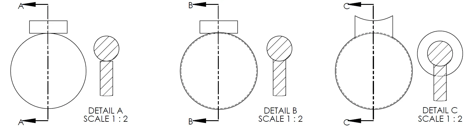
Figure 1 – Styles of worm gears
Why do I care about surface area? The ability to have the gear withstand greater torque. The more the surface area the greater the ability to share the love when it comes to higher torques. I do not foresee my gears requiring great forces, and I want to mesh directly to my spur gears created earlier, so I chose DETAIL A.
Modeling the worm gear
My worm gear will be only used at slow speeds with minimal load, so my gear will be more decorative than efficient. I did not worry about making it the same as one would make a commercial worm gear.
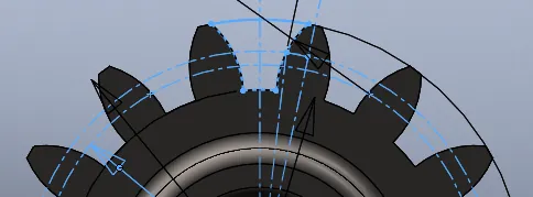
Figure 2 – Tooth Profile Sketch
To create my worm gear, I started with a cylinder using the length and diameter I wanted. I then added a Helix/Spiral with the pitch from the gear. And, I copied the tooth profile sketch from the gear this will be mating to. With that as my profile and the helix as the path, I did a Swept Cut.
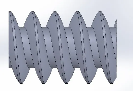
Figure 3 – After the Swept Cut
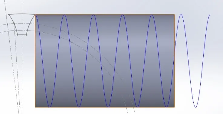
Figure 4 – Profile and Path for Swept Cut
I added a hole to receive the motor shaft and a stem to fit into the brace on the other side. Lastly, I tapered the ends with a Cut-Revolve to give it some extra shape.
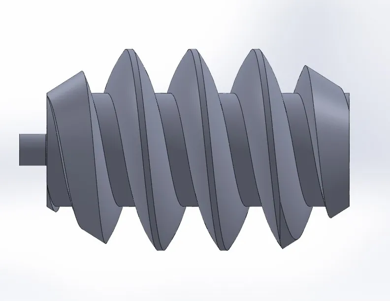
Figure 5 – Final Worm Gear
Next up in this blog series: Modeling the Fin.
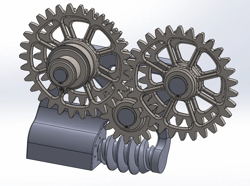
Figure 6 – All The Gearing
If you need technical help with SOLIDWORKS, please call our support line. We are ready to help at 1-888-559-6167.
Part 1: Kinetic Art Project: Intro
Part II: Kinetic Art Project: Toolbox Gears

About Brandon Harris
Brandon is a BYU-Idaho graduate with a Bachelor’s Degree in Mechanical Engineering. He is an avid tinkerer, and consummate rapid prototype hobbyist with prior experience designing for the Architectural/Construction industry. Brandon is part of the technical support team for GoEngineer serving as a PDM specialist since August 2018.
Get our wide array of technical resources delivered right to your inbox.
Unsubscribe at any time.