Creating a Non-Circular Helix in SOLIDWORKS with Surfacing Commands
The Typical SOLIDWORKS Helix
We all know how to make a helix in SOLIDWORKS, right?
- Sketch a circle
- Execute the Curves > Helix and Spiral command
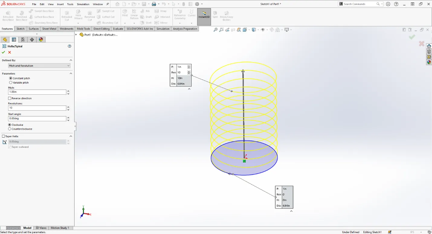
Well what if you needed to create a non-circular helix? Think squares, rectangles, slots, etc. How would you create that? The Helix command and Spiral command in SOLIDWORKS can only be created from a sketch circle. So, what are your other options?
 Recommended Video: Helix Along Path
"I’ll just sketch it myself, pattern a repeating group, and finish with a Sweep feature!”
Unless you want to spend your entire workday 3D sketching to extreme exactness this is not the best option.
To solve this conundrum, we’ll do what all good solid modelers do in a pinch: try surfacing commands!
In this post, I will illustrate an example of creating a rectangular spring in SOLIDWORKS using clever surfacing and curve commands.
How to Create a Rectangular Spring
- First off, if you want your spring to be vertical, start a sketch on the Right or Front Plane. Sketch a line that will be the length of your spring. In my example, it's 10”.
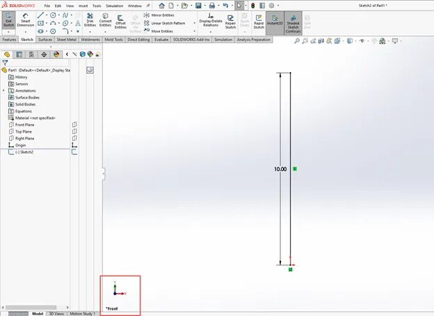
- Exit that sketch. That is your sweep path. Name it if you wish.
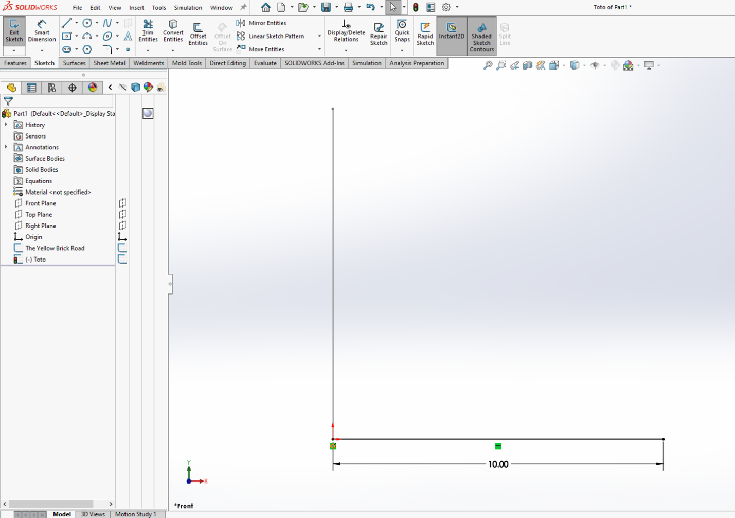
- Start a new sketch on the Front or Right Plane. It doesn’t really matter which one you use unless you care where the endpoint of your spring will be.
- Sketch a horizontal line to some arbitrary distance. It’s always best to use the Pierce relation for sweeps.
To learn more about the Pierce relation, watch the video below.
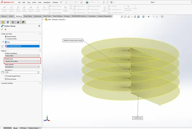
- After you have your two sketches, execute the Swept Surface command. Select the vertical line as your path and the horizontal line as your profile. Make it a less boring sweep by expanding Options and set Profile Twist to Specify Twist Value. Explore the options in Twist Control. For mine, I’ll use Revolutions and set it to 5.
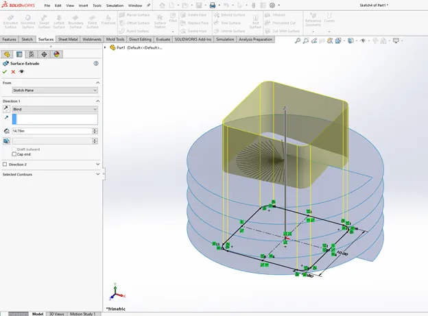
- Start a new sketch on the Top Plane. Dimension the spring and ensure that your profile is one continuous, tangent loop. Extrude through and past the Swept Surface.
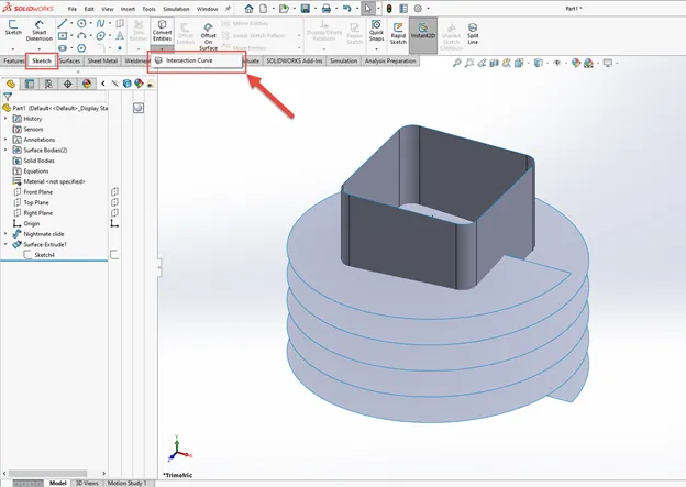
- This is where the magic happens. With your two intersecting surface bodies, execute the Intersection Curve command.
- Found under the Sketch tab under Convert Entities OR
- Found under Tools > Sketch Tools > Intersection Curve
- Be careful of your selection here. It will accept pretty much anything you click on. If you select a face, it will only use that face. For our intents and purposes, we need every intersection between our two surface bodies. Expand the Flyout FeatureManager Design Tree, expand the Surface Bodies folder, and select both bodies.
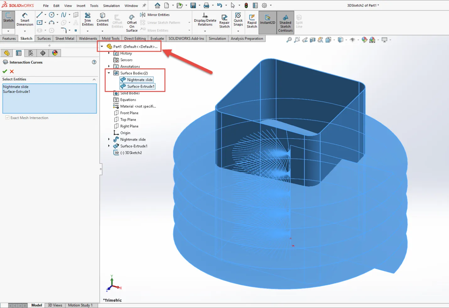
- You now have a 3D Sketch that is fully constrained by the intersection of your two surface bodies. Simply tweak the parameters in your two surface features to modify the dimensions of the spring.
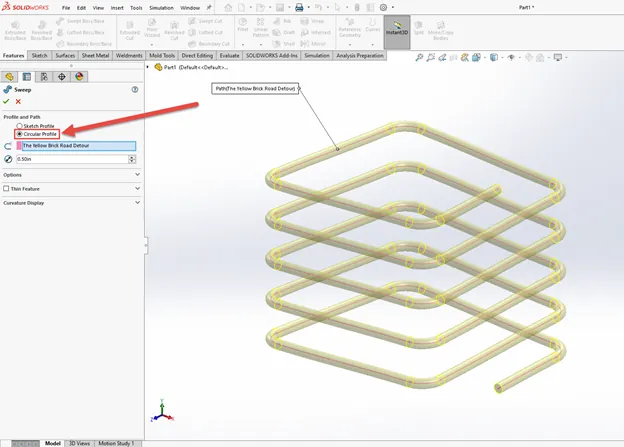
- Now all that’s left to do is create a Swept Boss/Base, set it to Circular Profile, select your 3D Sketch as your path, and set the diameter.
I hope you found this tutorial for creating a non-circular helix helpful! Check out more SOLIDWORKS tips and tricks below.
Learn New SOLIDWORKS Skills
Removing External References in SOLIDWORKS Files
How to Color Sketches in SOLIDWORKS
SOLIDWORKS Cosmetic Thread Upgrades
![]()
About GoEngineer
GoEngineer delivers software, technology, and expertise that enable companies to unlock design innovation and deliver better products faster. With more than 40 years of experience and tens of thousands of customers in high tech, medical, machine design, energy and other industries, GoEngineer provides best-in-class design solutions from SOLIDWORKS CAD, Stratasys 3D printing, Creaform & Artec 3D scanning, CAMWorks, PLM, and more
Get our wide array of technical resources delivered right to your inbox.
Unsubscribe at any time.