SOLIDWORKS Electrical 2020 Leader Lines – What’s New
SOLIDWORKS ELECTRICAL 2020 Leader lines
(Leader Jogs for the EE)
Creation of detail notes can be a chore. Now in SolidWorks Electrical 2020, Leaders for Notes and Blocks are here to help.
Whether 3D or 2D, you will have to deal with it. If your typical workflow involved creating individual arrowhead and line combinations, then trying to link that to text elements, you know what I’m talking about. And it never fails, as soon as you think you’re done, here comes the inevitable change request. Back to moving the elements and adjusting lines.
The new functionality is available in the cabinet layout and harness drawings in SolidWorks Electrical Schematic.
To access these tools, look to the Annotation section of the toolbar. There are options for “Text leader”, “Block leader”, and “Styles”.
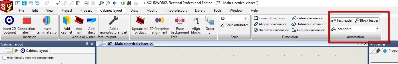
Figure 1 – cabinet layout view
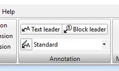
Figure 2 – scheme view
Within your project use the Tools tab and select Leader styles to manage the leader styles you prefer. You can also access the styles manager from the button next to the style name in the annotations area.
The insertion procedure of the text and block leaders, leader start, jog points, text location, and text or block information is prompted for consistent with the other SolidWorks Electrical tools.
Grip Selection 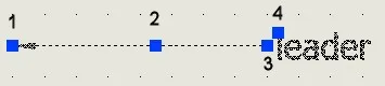
Callout Description
- Arrowhead
- Start point of the landing line
- End point of the landing line
- Text position
The graphical properties are also available in the properties tab format. The options for General, Overall, and Leaders are common to both text and block forms. Instance appropriate text or block areas have additional properties.
.jpg?format=webp)
Figure 3
SOLIDWORKS Electrical 2020 Leader Styles
In reviewing the use of these tools, I believe the best place to start is really with the Leader styles.
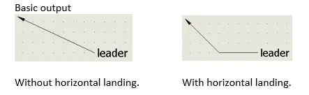
Out-of-the-box there are several built-in styles that are not editable. There are options for the basic straight leader, multi-jog, and an additional landing zone style (adds a visual lead-in relief for the leader connection).
However, you can create what you need to better fit your documentation requirements. The defaults, with a little adjustment, are adequate for some situations, but from my experience if you need to locally edit a standard after insertion more than a few times, you should create a style for it.
Leader Styles Manager
The leader styles manager can be accessed either from the Tools menu ribbon, or from the associated button in the annotations section (next to the style name).
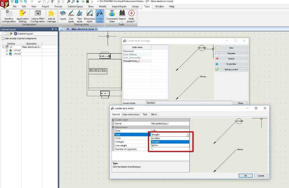
Figure 4
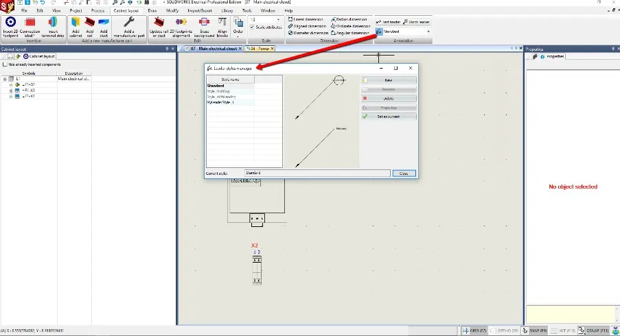
Figure 5
To create one of your own, make a copy of one of the defaults. Set one of the defaults as current and select new. Assign a new name and adjust the properties from there.
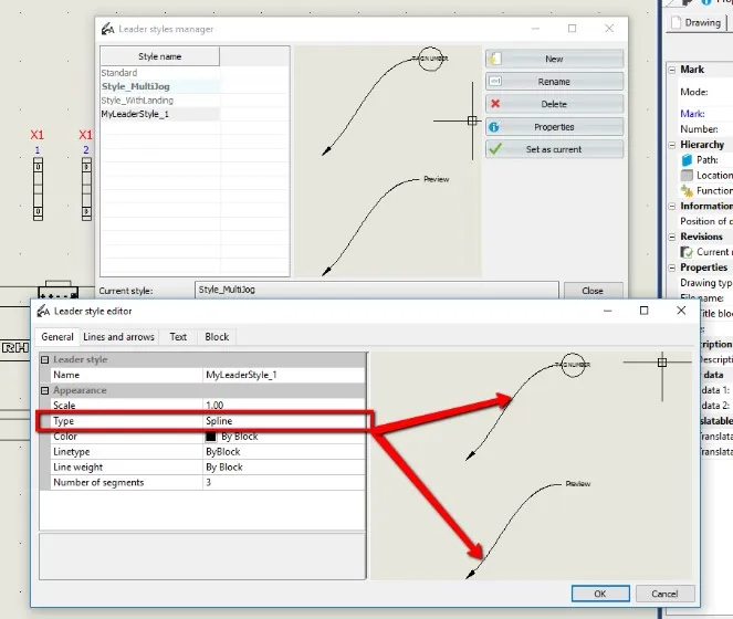
Figure 6
Additionally, there is a provision for using a spline and specification of the number of segments to create, as with the multi-jog option. When drawing specifications require it, in a densely packed drawing, to draw attention to an important detail, or just for something non-orthogonal.
In my review cabinet layout, I have a power supply and two terminals. I would like to place a text box and a spline leader to note the footprint symbol should be updated. I first created the leader style using a copy of the multi-jog style, reduced number of segments, and selected splines. On insertion I am prompted for the arrow point, spline points, and then the text annotation.
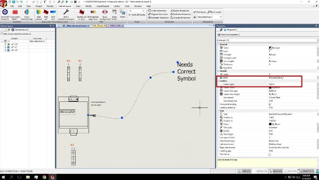
Figure 7
Once placed, the individual elements can be adjusted through the properties manager.
During the collaborative process these notes between designers, or as an integral part of the documentation, can save hours of mis-spent effort, and prevent costly mistakes.
There are many ways this tool can be implemented, far too many to go through here. I will trust our user community to explore the limits.
Added reviewer note
I have also found these features available in line diagrams (mixed scheme) and standard schemes. Another area that could always use a little extra detail at times.
Having seen the evolution of this product in the last several years, I can say this feature addition is due in large part to the user-base requests. If there is a new functionality you think would improve the software functionality, the development team would like to hear from you.
To make your voice heard please take a few minutes to submit that enhancement request for the feature you would like to see added or improved.
The addition of any additional or improved functionality is always welcomed through the SW Customer Portal enhancement requests link. Your input carries more weight than you may realize.
This evaluation was conducted on a Beta version.
Interested in learning more about what’s new in SOLIDWORKS 2020, check out our collection of videos here.
![]()
About Martin Adams
Martin Adams is a Senior Technical Support Engineer at GoEngineer supporting SOLIDWORKS CAD and SOLIDWORKS Electrical products. In addition to a CSWE certification, he has a Bachelor's degree in Industrial Engineering and an Electrical Associate's degree. Prior to joining GoEngineer in 2019, he worked for almost twenty years on prototype automotive instrumentation. He also served as an Electrician's Mate in the US Navy. His favorite activities are fishing and spending time around a campfire with friends.
Get our wide array of technical resources delivered right to your inbox.
Unsubscribe at any time.