SOLIDWORKS Motion: A Tip for Handling Performance "Hogs"
J. Michael McCarthy of University of California Irvine (UCI) teaches a course focused on the design of walking machines. These walking machines have a lot of components and mates, so simulating them using SOLIDWORKS Motion Analysis can be a huge performance “hog”. In this article, we show a technique that is used to simplify assemblies and make this hog run fast.
original Assembly
The model originally developed by Kevin Chen at UCI started out looking like what is shown in Figure 1 below.
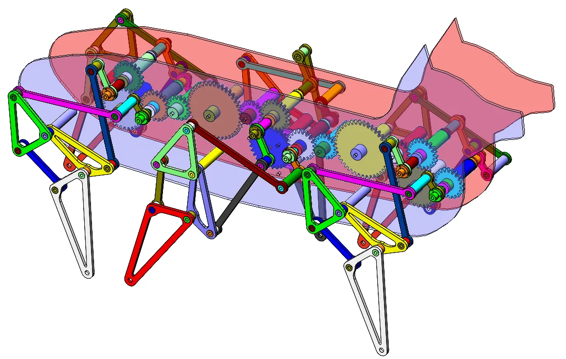
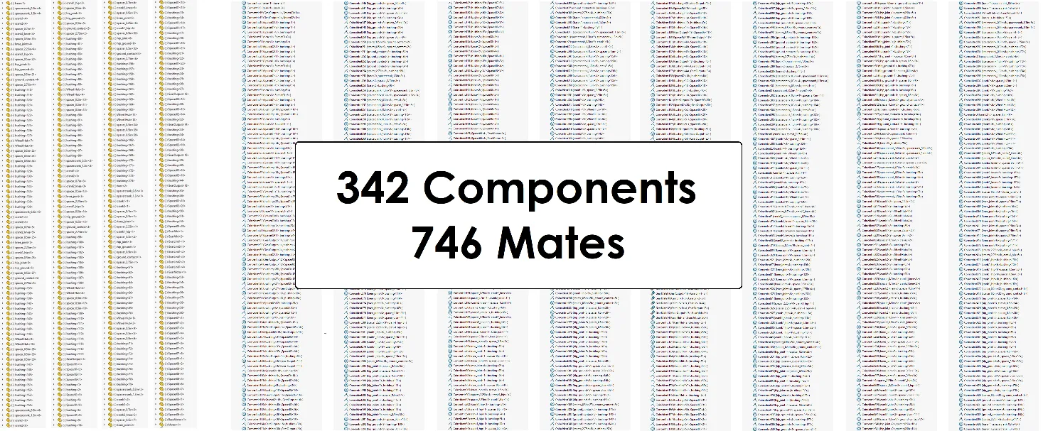
Figure 1 - Original assembly structure.
All the components in this assembly are parts. Note: if you use some Flexible Subassemblies for your components, all the subassembly mates will be solved in the main assembly just like the rest of the components.
Motion Analysis Errors and Troubleshooting
When we tried to run a Motion analysis using this assembly, we got error messages like the one in Figure 2 below.
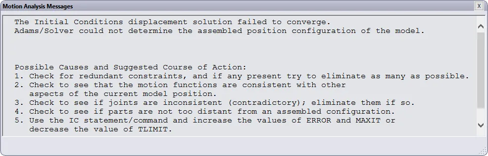
Figure 2 - Motion analysis errors.
In this case, the software warns about their being redundant constraints. For troubleshooting, we enabled the option called “Replace redundant mates with bushings” below and tuned some of the settings (Figure 3) to try to force the Motion analysis to run.
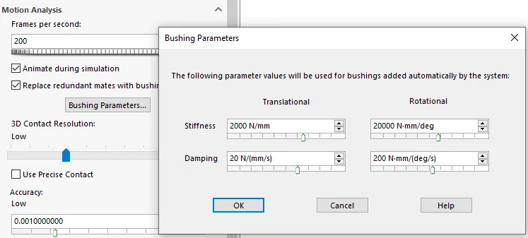
Figure 3 - Tune motion settings.
After a lot of trial and error we got a result that looked like Figure 4 below.
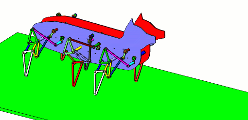
Figure 4 - Results on original model.
A couple problems with this analysis:
- It took about 2000 seconds just to get 1 second of results. This means a 10 second simulation takes hours to run!
- A lot of trial and error of the bushing parameters, contact, and precision was required.
- The joints are flexible since we turned on the “Replace redundant mates…” option. You can see some of them slip a little. Look carefully at the rotation of the rear leg gear shaft.
Simplify the Model
To make this Motion Analysis work more easily, we reduced the component count in the assembly. Fewer components will mean fewer mates that Motion Analysis will need to solve. One way to reduce components is to group components that move together. See if you can spot this grouping in the example animation shown in Figure 5.
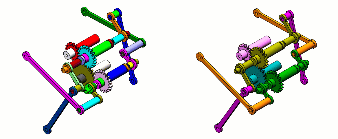
Figure 5 - Group components that move together. Left: Without grouping (color-coded); Right: With grouping (color-coded).
One technique to perform this grouping is to select the components and select “Form New Subassembly”. The animation showing this step (see Figure 6) transforms seven components into one component.
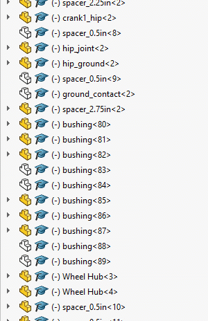
Figure 6 - Form new subassembly to group components together.
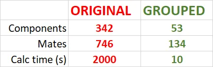
After we completed the grouping, now the assembly tree is a lot easier to manage and our Motion Analysis must solve only 134 mates instead of the 746 that we had originally.
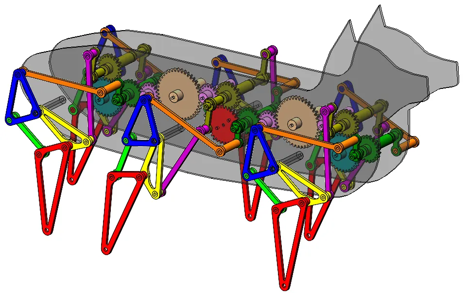
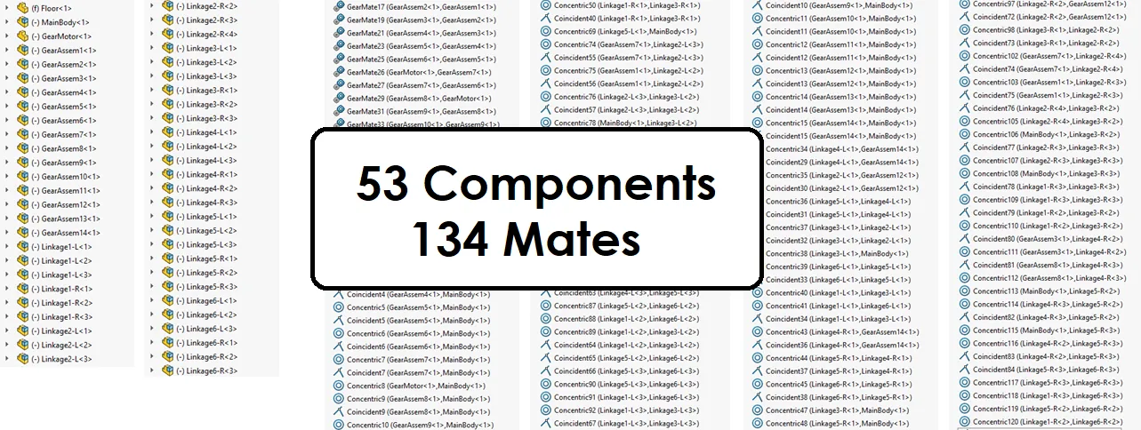
Figure 7 - New assembly structure.
Results and Comparison
To get this study to run, no special settings or trial and error were required, and the calculation was complete in seconds. The results are shown in Figure 8.
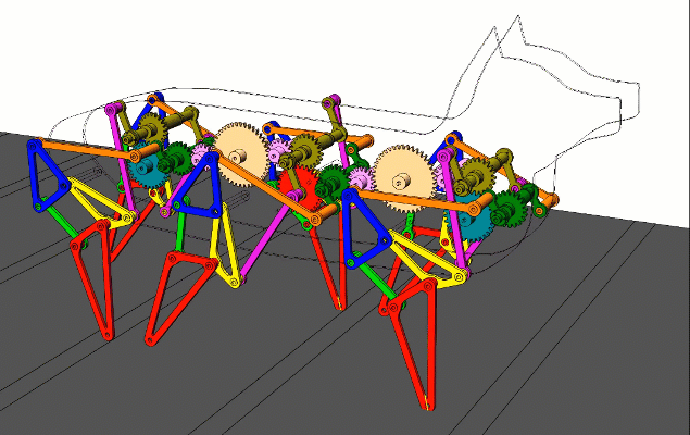
Figure 8 – Grouped motion results. We added a camera to follow the hog along its path.
For comparison, the statistics of these two assemblies are shown side-by-side in the table below.
Summary
Setting up Motion Analysis on large assemblies can be easy, but you may need to group your components together to reduce the overall component and mate count. A great way to perform this grouping is to use subassemblies, but this is not the only way to do it (see Rigid Groups).
To learn more about SOLIDWORKS Motion, consider checking out our YouTube channel or schedule an Application Mentoring Session with one of our Application Engineers. You can check out more of these types of mechanisms here to see a few of them in action.
Note: This model was designed by Kevin Chen at University of California Irvine
More SOLIDWORKS Tips & Tricks
Frequency Study Plot with SOLIDWORKS Simulation

About Shaun Bentley
Shaun Bentley is passionate about applied mathematics and engineering, which led him to pursue and understand real world applications of FEA, CFD, kinematics, dynamics, and 3D & 2D modeling. He teaches many simulation classes to both new and advanced users attending training at GoEngineer. Since 2006, Shaun has been working with simulation tools to solve real world engineering problems. With every new project, he seeks to find ways to push simulation to its uppermost limits, even going so far as to write bespoke code and macros. He has passed the Michigan FE exam and mentors or consults for virtually any industry that uses SOLIDWORKS, especially automotive and automated tools. He is a speed 3D modeling champion and one of the first Certified SOLIDWORKS Experts in Simulation in the world.
Get our wide array of technical resources delivered right to your inbox.
Unsubscribe at any time.