SOLIDWORKS Simulation Load Case Manager
SOLIDWORKS Simulation 2015 introduced a new utility called the Load Case Manager. It is available within a linear static study and is included in the SOLIDWORKS Simulation Professional and Premium packages. This utility allows for the creation of secondary load combinations from primary load cases to quickly evaluate the effects of various load combinations on your model. This article will cover how to access and manipulate the settings within the Load Case Manager.
Accessing the Load Case Manager
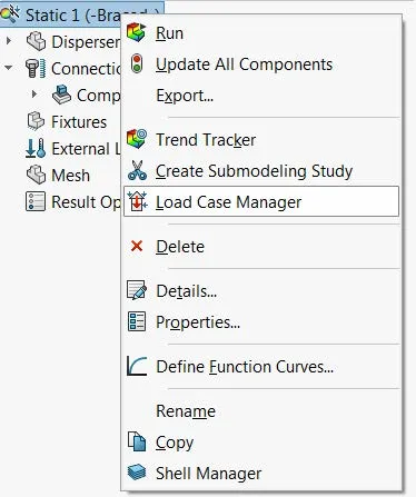
The Load Case Manager can be accessed by right-clicking the top icon in a linear static study tree.
Load Case View
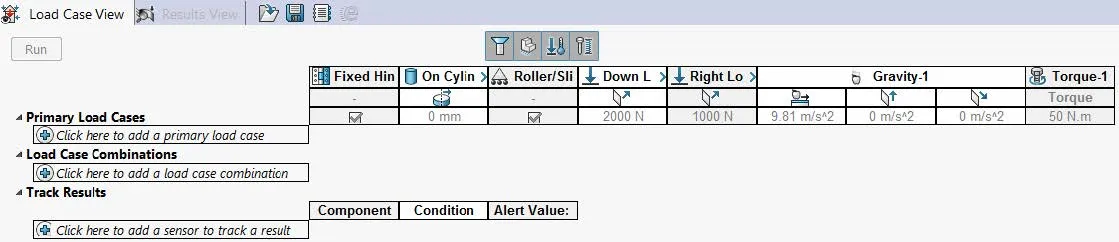
The load case view tab allows for the specification of the load case manager settings. It is broken into three sections: Primary Load Cases, Load Case Combinations, and Track Results.
Primary Load Cases
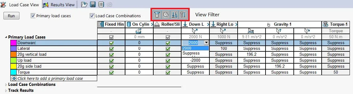
The primary load case section allows for setting up different analysis scenarios. All of the study fixtures and loads are available. You can define as many loads as needed to simulate different scenarios. The suppression state and values can be individually controlled for each primary load case.
As of SOLIDWORKS 2016, the bolt connector is the only connector type available. The preload value used for bolt connectors is available to adjust per primary load case.
Load Case Combinations
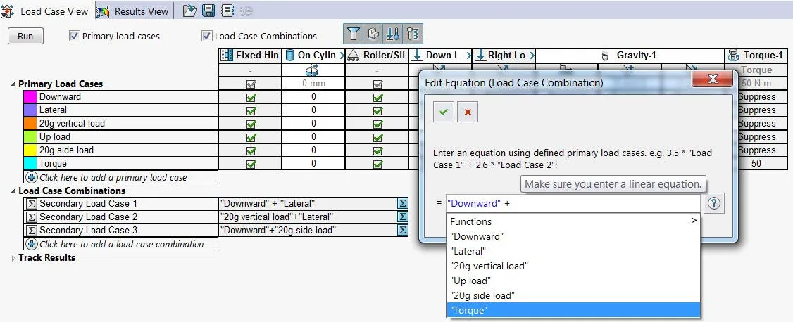
The load case combinations section allows for setting up different load combinations. Simple mathematical equations can be defined to relate different primary load cases together. Each of the primary load cases is solved individually and then the load case combinations are calculated.
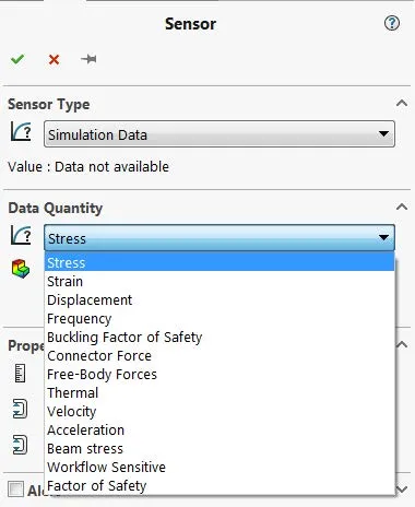
Track Results
Sensors can be defined to track certain SOLIDWORKS Simulation result data.
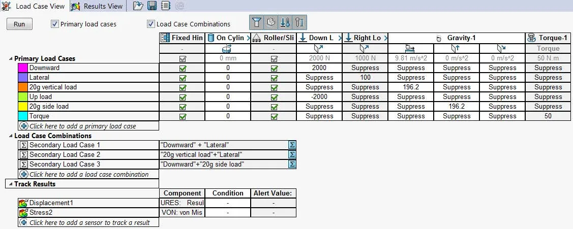
There is no limit to the number of sensors that can be defined. Sensors can be set up to track stress, strain, displacement, bolt connector forces, etc.
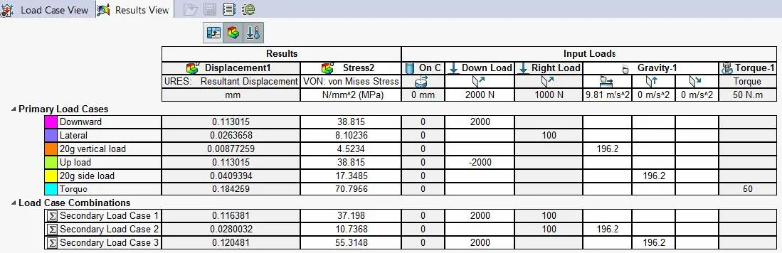
Results View
The view lists out the tracked sensor results.
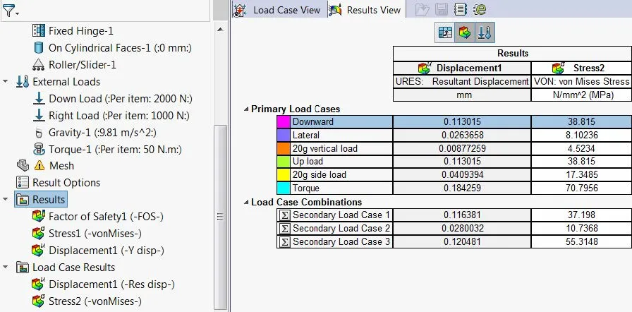
In the left-hand pane, result plots can be shown under the results section or the load case results section. New plots can be created by right-clicking on the results link.
In order to view result plots, one of the primary load cases or load case combinations have to be highlighted. If a result plot is displayed, switching to another primary load case or load case combination will automatically update the result plot. If a plot is activated under the results link, then all post-processing options are available (edit definition, section clipping, iso clipping, etc.).
Learn More About SOLIDWORKS Simulation
What Determines the Default Mesh Size in SOLIDWORKS Simulation?
Why Use Hex Elements in Your FEA?
Introduction to Validation Equations in SOLIDWORKS Simulation
SOLIDWORKS Simulation Results Export Options
![]()
About GoEngineer
GoEngineer delivers software, technology, and expertise that enable companies to unlock design innovation and deliver better products faster. With more than 40 years of experience and tens of thousands of customers in high tech, medical, machine design, energy and other industries, GoEngineer provides best-in-class design solutions from SOLIDWORKS CAD, Stratasys 3D printing, Creaform & Artec 3D scanning, CAMWorks, PLM, and more
Get our wide array of technical resources delivered right to your inbox.
Unsubscribe at any time.