Toolbox Gears – Kinetic Art Project Part II
Thank you for returning to my Kinetic art project series. This blog is focused on the SOLIDWORKS Toolbox. You can catch Part 1, Kinetic Art Project: Intro, here.
What I Learned about Toolbox Gears
Creating gears in SOLIDWORKS can be intimidating especially for the first time. Thankfully SOLIDWORKS Toolbox does most of the hard work for you.
Diametral Pitch
Diametral pitch equals the number of teeth divided by the pitch diameter; the result is the size of the gear tooth independent of the size of the gear.
What this means to non-engineers is that so long as two gears have the same diametral pitch, they will properly mesh. Larger diametral pitch numbers result in smaller gear teeth. For my gears, I wanted nice large teeth, so I chose a smaller diametral pitch of five.
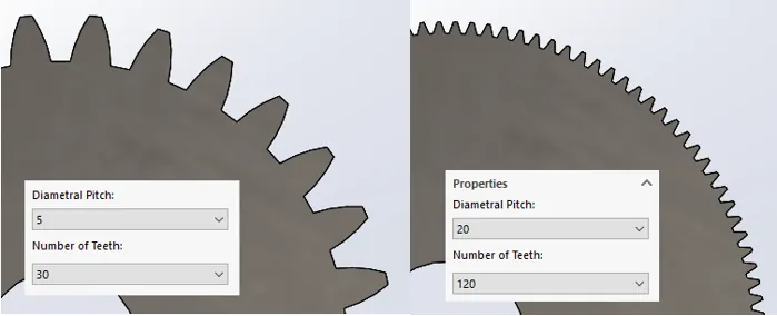
Figure 1 – Two gears that are the same size with different Diametral Pitch
Tooth Count
Obviously, the tooth count is the number of teeth on your gear; this number will govern the size of the gear. The diameter of the gear will be the number of teeth divided by the diametral pitch.
So, if I have a gear with 30 teeth and a diametral pitch of five teeth per inch, the diameter will be six inches.
30/5=6”
If I have another gear with 20 teeth, and the same diametral pitch as above, the diameter will be four inches.
20/5=4”
Technically, this is the pitch diameter and not the overall diameter (See Figure 2).
With the pitch diameter, it is easy to calculate the center-to-center distances of the gears. Consider the two gears in Figure 2. First, divide them in the individual diameters by two to get the radius:
6”/2 = 3” and 4”/2 = 2”
Now add the radii:
3”+2” = 5”
This is the center-to-center distance as shown below in Figure 2.
Figure 2 – Calculating the center-to-center distance.
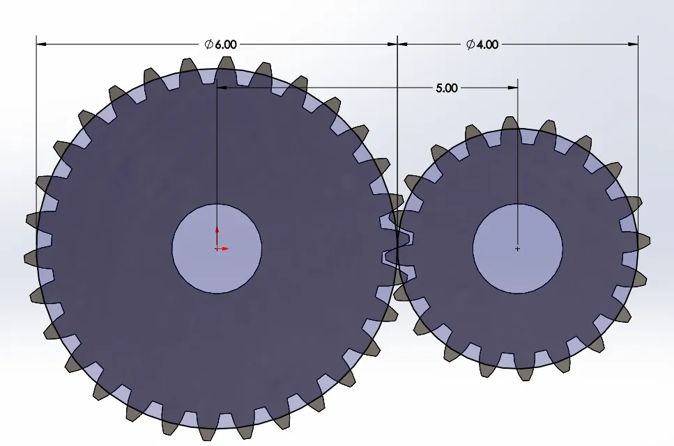
Figure 2 – Calculating the center-to-center distance
Because tooth count is proportional to the size of the gear, you can also use the number of teeth to calculate the gear ratio. Using the gears we created, the gear ratio will be 30:20 or 3:2.
Read Only
Toolbox files are read-only. The toolbox will override any changes made to a toolbox part, but I think the default Toolbox gears are ugly. So to make them look better, you need to change the setting in the System Options – Hole wizard/Toolbox.
Uncheck the box called Make this folder the default search location for toolbox components. This allows you to do a Save As on the part file, and save it to your project folder.
SOLIDWORKS still thinks this is a toolbox file, and we need to remove the toolbox identifier attached to this file. To do this, navigate to C:\Program Files\SOLIDWORKS Corp\SOLIDWORKS\Toolbox\data utilities. (This path may change depending on your installation.)
Run the sldsetdocprop.exe. Now you have a part that was created by the toolbox but is no longer governed by it. (Note: I added some cuts and fillets to add character to my gears.)
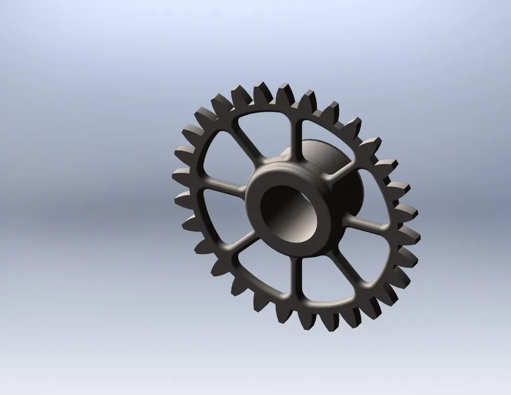
Figure 3 – Finished Gear
In my next blog, I we discuss worm gears.
In the meantime, if you need technical help with SOLIDWORKS, please call our support line. We are ready to help at 1-888-559-6167.

About Brandon Harris
Brandon is a BYU-Idaho graduate with a Bachelor’s Degree in Mechanical Engineering. He is an avid tinkerer, and consummate rapid prototype hobbyist with prior experience designing for the Architectural/Construction industry. Brandon is part of the technical support team for GoEngineer serving as a PDM specialist since August 2018.
Get our wide array of technical resources delivered right to your inbox.
Unsubscribe at any time.