A Guide for Using Bearing Connectors in SOLIDWORKS Simulation
What do bearing connectors do? When using SOLIDWORKS Simulation, a bearing connector simulates the support and movement between a housing support and a shaft, without needing a physical bearing component. This is a little different than a bearing fixture.
A bearing fixture assumes that the housing support is much more rigid than the shaft, so its flexibility is not important and it can be considered ground. So, when the housing support isn’t rigid and its flexibility needs to be taken into consideration, you will want to use a bearing connector. When using a bearing connector, both the shaft and the housing support will need to be modeled.
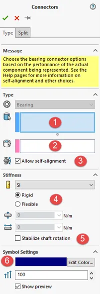
Creating a Bearing Connector and Its Options
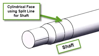
- For shaft: Cylindrical face or circular edges of a shell.
- Create split lines on the shaft to define which portion of the shaft will be in contact with the ‘bearing’ that then connects to the housing.
- Create split lines on the shaft to define which portion of the shaft will be in contact with the ‘bearing’ that then connects to the housing.
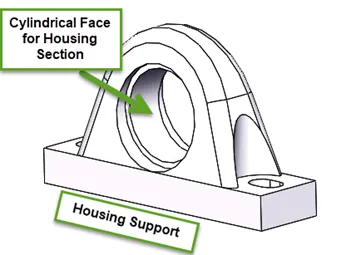
- For housing: Cylindrical face or circular edge of the shell.
- Self-Alignment Options: This decides whether the alignment allows for a nonrestrictive off-axis rotation or not.
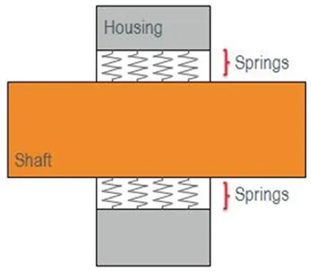
- Allow Self-Alignment’ Disabled: This does not allow off-axis rotation of the shaft. It is related to a needle or roller bearing and is represented by springs that are evenly distributed radially around the shaft and projected towards the housing support. A visual of this option is shown in the picture below.
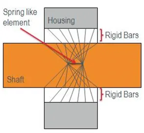
- 'Allow Self-Alignment’ Active: This allows off-axis rotation of the shaft. This means that the bearing is not sensitive to the misalignment of the angles between the housing and the shaft. This allows for no resistance to the bending deformation of the shaft. It is related to a self-aligning bearing with a couple of rows of balls that align on concave sphered raceways on an outer ring. It is represented by a spring-like element that allows stiffness in the radial and axial direction and is connected by rigid bars across the entire surface of the shaft and projected to the housing support. A visual of this option is shown in the picture below.
- Allow Self-Alignment’ Disabled: This does not allow off-axis rotation of the shaft. It is related to a needle or roller bearing and is represented by springs that are evenly distributed radially around the shaft and projected towards the housing support. A visual of this option is shown in the picture below.
- Stiffness Options
- Rigid: This option creates a high stiffness value to all the springs (when it is none self-aligning) or the spring-like element (when self-aligning). Will not be able to move axially or radially.
- Flexible: This option allows the adjustment to the stiffness of the springs for the lateral to allow it to deform and axial stiffness to allow it to displace.
- Stabilize Shaft Rotation
- When this is selected it will prevent the shaft from being about to rotate freely and eliminates instability, this acts as a pin connector not being able to rotate.
- Symbol Settings
- These control the color and the size of the arrows that appear when displaying the connection.
Guidelines for Using Bearing Connectors
- Physical bearing geometry is not needed to use the bearing connector, if some are already defined, they will need to be suppressed in the FeatureManager Tree.
- Use split lines on the shaft to define the contact between shaft and housing support.
- Create separate bearing connections for each connection between two bodies.
Analyzing the Results
- When probing results for the bearing connector, make sure to probe them far away from the connector, or else you may capture stress concentration effects.
- Bearing forces that are on a connector are shear force, axial force, and a bending moment. Torque is not a valid result as bearings are not designed to provide a significant amount of torque.
- To view the forces in each of the bearing connectors, right-click on the Results folder and select ‘List Connector Force’.

More SOLIDWORKS Simulation Tutorials
Frequency Study Plot with SOLIDWORKS Simulation
Offloaded SOLIDWORKS Simulation
7 Steps to Perform a Fatigue Analysis in SOLIDWORKS Simulation

About Tashayla Openshaw
Tashayla Openshaw is a SOLIDWORKS Technical Support Engineer based out of our Headquarters in Salt Lake City, Utah. She earned her Bachelor’s degree in Mechanical Engineering from the University of Utah in 2018 and has been part of the GoEngineer family since February 2019.
Get our wide array of technical resources delivered right to your inbox.
Unsubscribe at any time.