Why Won't my Wires Route in SOLIDWORKS Electrical - Part 1
If you have ever tried routing wires in SOLIDWORKS Electrical, then you know how awesome they look when complete – but it can sometimes be a challenge getting there. In this SOLIDWORKS Electrical tutorial, I’ll share a few items to keep in mind when routing wires that will make the task easier. Let’s look into SOLIDWORKS Schematic and SOLIDWORKS Electrical 3D for these key tips!
A lot of time can be spent trying to get wires to route. One missed item can cause hours of frustration. Trust me, I know – I have had those times before. If a process is followed, then problems are caught before they can wreak havoc with your design. Even the most experienced designer can sometimes miss that one key component that will allow for a completely routed design.
Here are some items that are required for a successful 3D assembly of an electrical wire or harness.
Wires
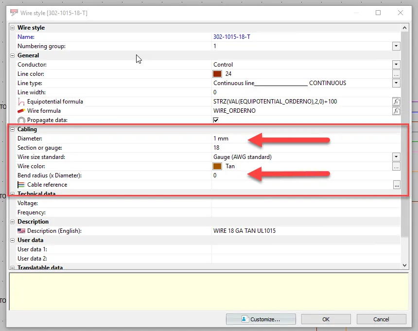
The wire plays a key role in the router for obvious reasons. Wire style properties are required for SOLIDWORKS to be able to establish a corresponding sub-assembly. The “Cabling” section of the properties holds the information required for the 3D modeling aspect of the assembly. The Bend Radius and Diameter are now critical items. The Color is not so critical but is utilized during the routing process.
Components
The wires of a route must be connected to “something” on both ends for the route to be successful. This “something” is a Component .
The Component provides the circuits and the connection points. These circuit and associated connection points are determined by the Manufacturers part that is assigned to the Component.
When creating schematics, you will be utilizing the symbols to represent the Component. The symbols also have circuits and connection points. When trying to route, make sure your Component circuits and connection points are associated with the circuits and connection points of the symbols that are being used.
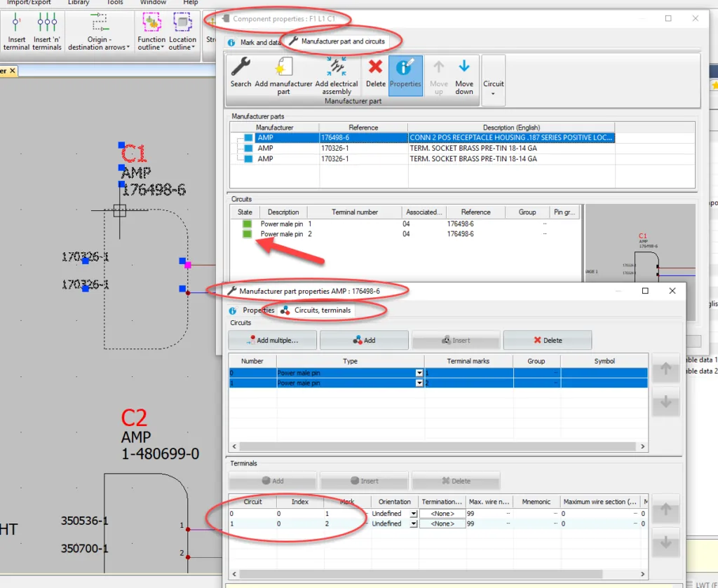
In other words, when examining your Component – are the circuits and terminals (that are used in the schematics) in the bottom of the dialog box GREEN? (Note: if they are BLUE, they will not affect your route and are commonly known as Spare circuits). If you don’t have all GREEN or BLUE circuits, then some corrections may be necessary. If they are all GREEN, double-check the numbering of these circuits, as they will be carried into the 3D model next.
3D Models
In the image above you can see the circuit terminals called out. This specific component has two circuits numbered “0” and “1”. Each circuit then has one connection point named Index. Therefore, this component has two connection points known as “0_0” and “1_0”. These connection points need to match the features inside of a 3D model that will be representing the Component.
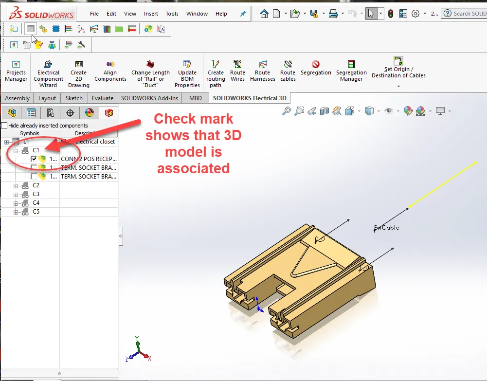
SOLIDWORKS Electrical 3D utilizes a Routing Wizard to help assist with the process of adding these connection points to the 3D model. The connection points are added to the model as Features.
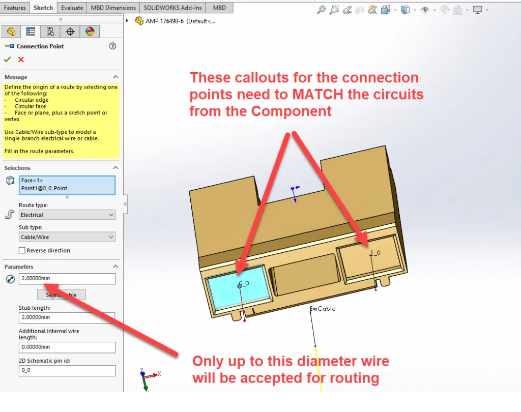
Once you have opened the 3D model, editing each Feature will allow you to examine its parameters, such as Diameter. This parameter is a maximum setting for the acceptance of this connection. The Diameter must be able to accept the wire diameter that you are trying to route to it. Be sure to check that the features have all of the connection points called out correctly. In my example, we need to have a 0_0 and 1_0 feature.
There are a few more key points that should be considered. For more information on these crucial items stay tuned for part 2 of this series.
Want more SOLIDWORKS Electrical tutorials? Visit our YouTube Channel !
I hope you found this SOLIDWORKS Electrical tutorial helpful. For more SOLIDWORKS tips and tricks please subscribe!

About Cheri Guntzviller
Cheri Guntzviller is a Senior Electrical Specialist with over 35 years’ experience. She earned her Bachelor of Science in Electrical Engineering degree from Lawrence Technological University and joined the VAR channel in 2013 with DASI (now GoEngineer). She is a problem solver and is passionate about teaching and helping others solve problems. Based out of Michigan Cheri enjoys gardening, fishing, construction, and spending time with her family and pets. Cheri is a SOLIDWORKS Certified Electrical Specialist, Trainer, and Professional Presenter.
Get our wide array of technical resources delivered right to your inbox.
Unsubscribe at any time.