3 SOLIDWORKS Surfacing Tools to Try
SOLIDWORKS has powerful solid modeling tools that can help create virtually any shape or design imaginable. However, you may get stuck trying to accomplish something, and all the solid modeling tools you've tried, won’t do the trick. In times like these, use SOLIDWORKS Surfacing tools!
SOLIDWORKS Surfacing tools are incredibly useful when solid modeling just isn’t enough. However, it can get very messy very fast. SOLIDWORKS Surfacing tools should be used sparingly and only when necessary. However, they can be a niche solution in a tight spot.
In this article, you'll learn about three useful SOLIDWORKS Surfacing tools and techniques to start incorporating into your modeling:
- Copy Surface (using Fill & Knit)
- Delete Face
- Move Face
Hopefully, they will spark your interest in further exploring the SOLIDWORKS Surfacing features.
SOLIDWORKS Surfacing tools location
Rather than go through a menu for every feature, enable the surface features tab in your SOLIDWORKS CommandManager by right-clicking any of the tabs and checking Surfaces.
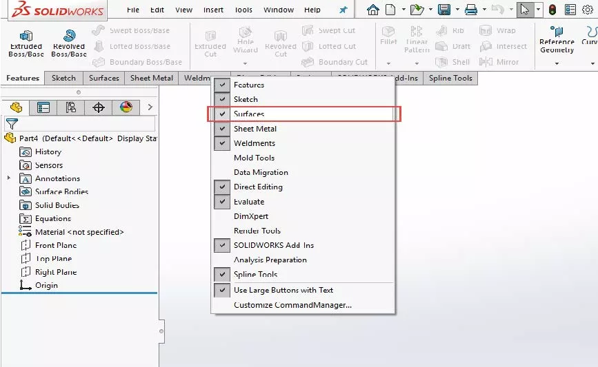
Figure 1: Enabling the Surfaces features tab in the CommandManager
It is also useful to set your Surface and Solid Bodies folders to always show in the FeatureManager. Go to Tools > Options > FeatureManager and set the Solid Bodies and Surface Bodies folders to Show.
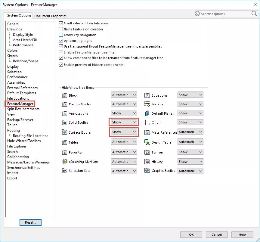
Figure 2: SOLIDWORKS System Options window
In your FeatureManager, you will now see this:
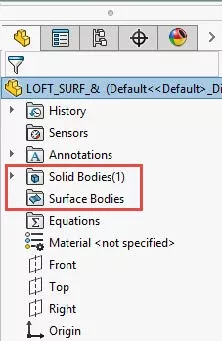
Figure 3: FeatureManager now showing Solid Bodies and Surface Bodies
When you begin to incorporate hybrid modeling, your end result should always be a solid body. Ensuring that the Surface Bodies folder always shows will be an easy check to know that you have successfully transitioned back to a solid body.
#1. Copy Surface to Analyze Internal Geometry
There are many ways to create features of internal geometry. One useful surfacing tool is the Copy Surface feature. For example, I have this part:
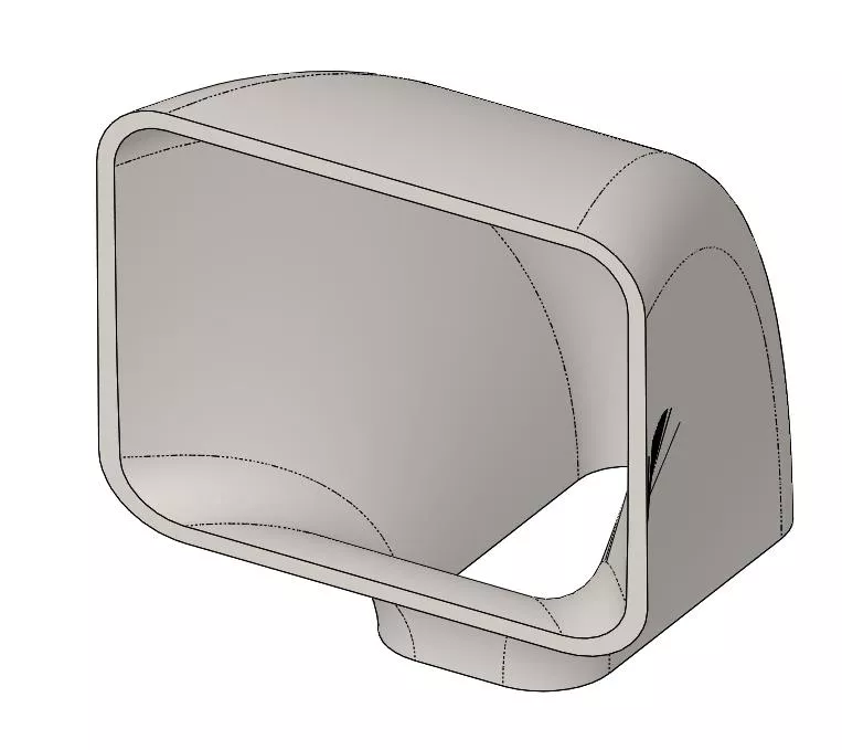
Figure 4: Example part
I want to create a male part and calculate the internal volume.
- To start, I insert the Offset Surface feature and select all internal faces.
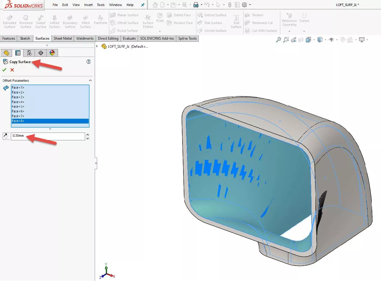
Figure 5: Offset Surface changes to Copy Surface - When I set the distance to zero, the Offset Surface feature changes to Copy Surface... This is exactly what I want.
- Now that I have copied the internal faces, I hide the solid body. Now only the recently created surface body should be visible.
- Next, I need to complete the surface so it encloses a volume. In this example, all I need to do is add two planar surfaces to both openings. I insert the Planar Surface feature and then select all the bounding edges.
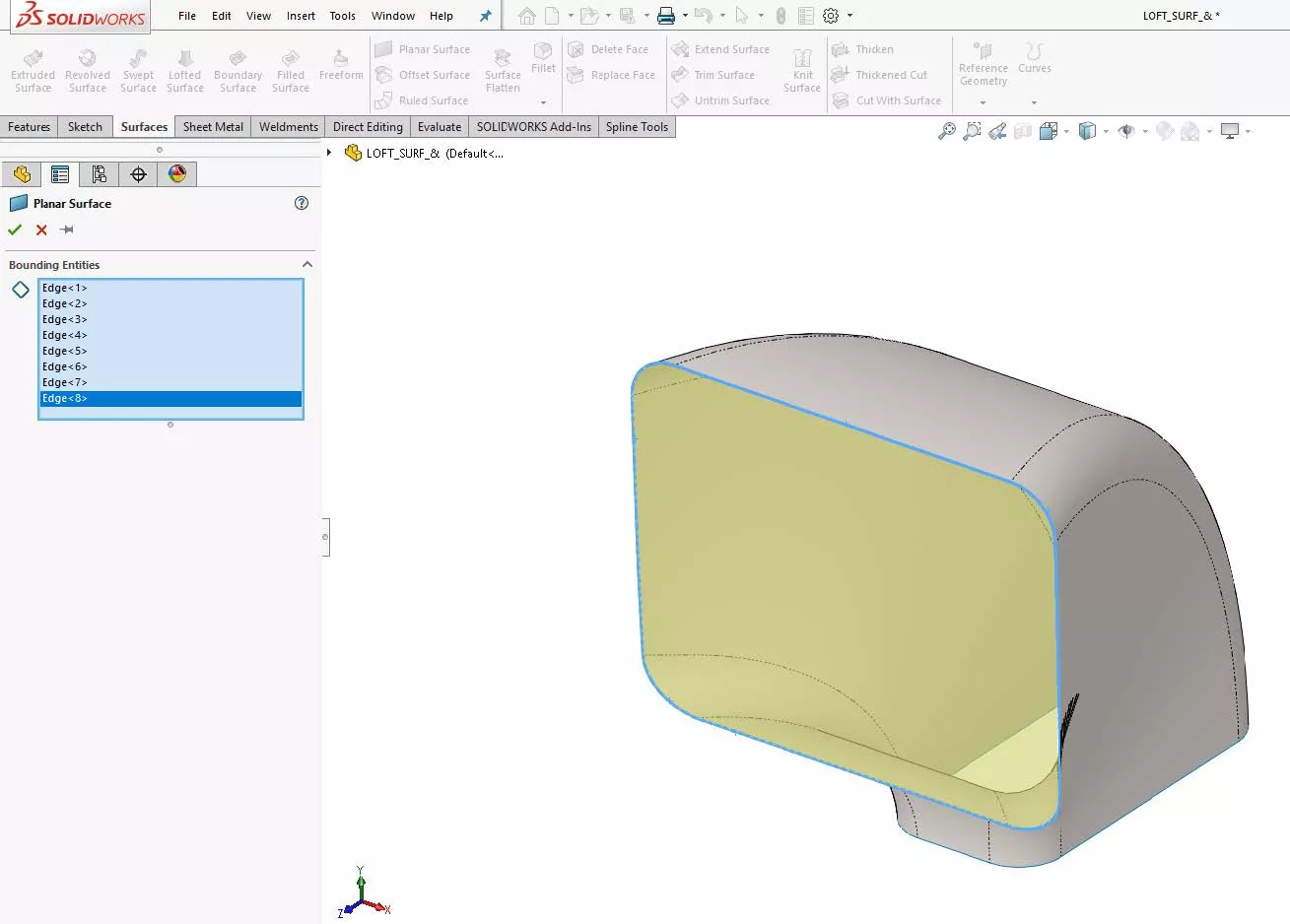
Figure 6, Inserting surfaces to enclose the volume - In other applications when the surface is not planar, you may want to insert a Surface Fill feature and make the edges tangent to the edges you select.
- All that is left to do is to knit the surfaces together and create a solid. I insert the Knit Surface feature and select all the surfaces. If I have done it right, there will be an option available called Create solid.
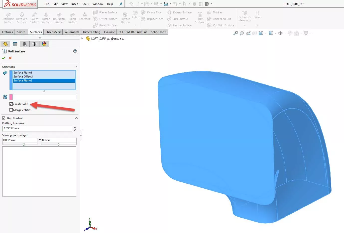
Figure 7: If you have a surface body that encloses a volume, the ‘Create solid’ option will appear - If you do not see the option, this indicates that you have an open surface. You can use the Check feature in the Evaluate tab and check the option Open surface(s) to locate it.
- If done correctly, I should now have a perfect male part. I can use the Mass Properties tool on the Evaluate tab to calculate the volume of the solid.
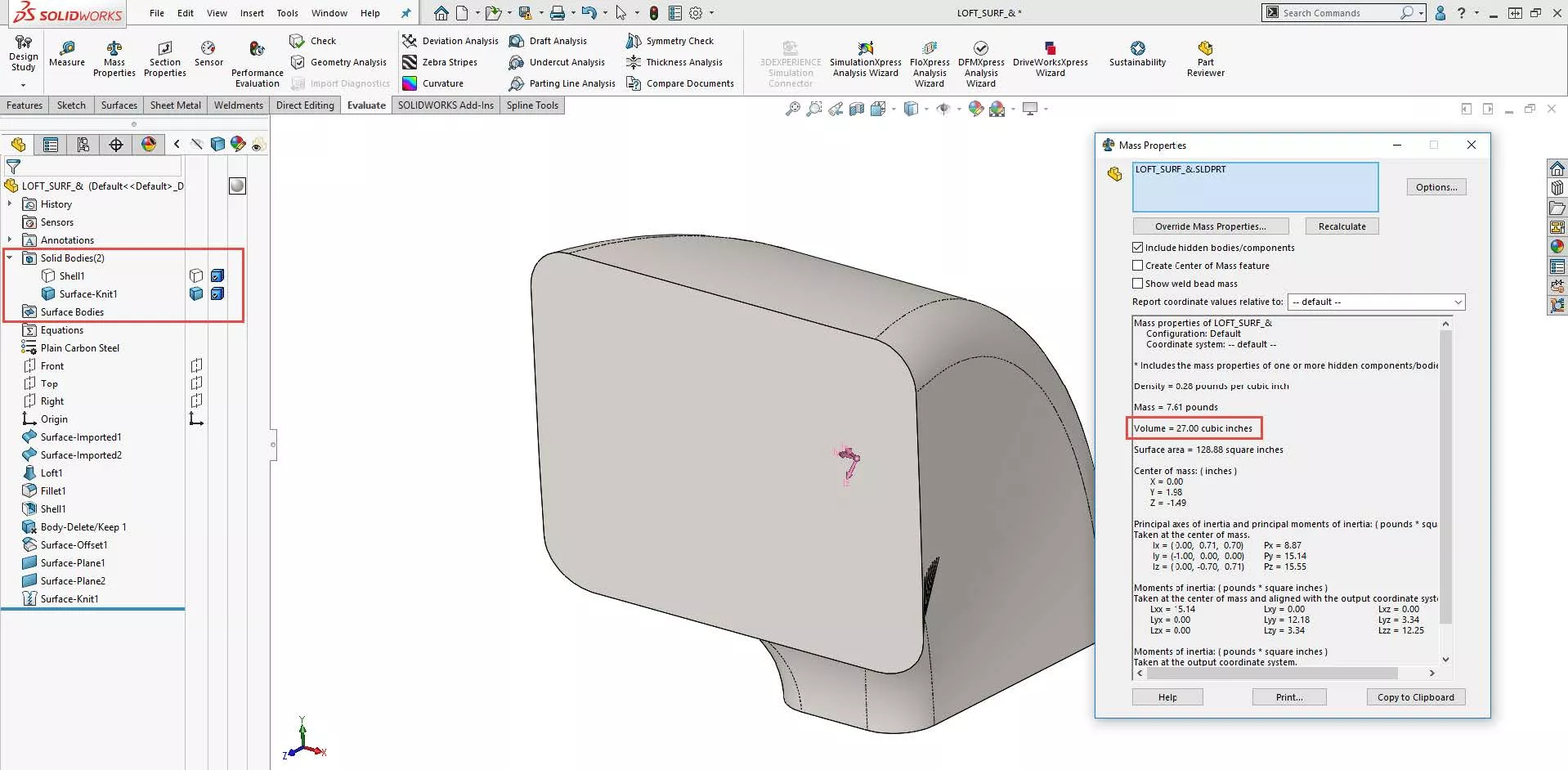
Figure 8: A completed male part of internal geometry that allows us to compute the volume - You will notice that the Surface Bodies folder is empty and we are left with a solid body.
#2. Removing Geometry With No Trace: Delete Face
In some cases, the desired result is to remove geometry from a part and leave no trace of its existence. This can be done by rolling back and deleting the original features, but this may cause trickle-down problems with subsequent features. In this instance, the Delete Face feature is a niche tool. In this example, I will use this part:
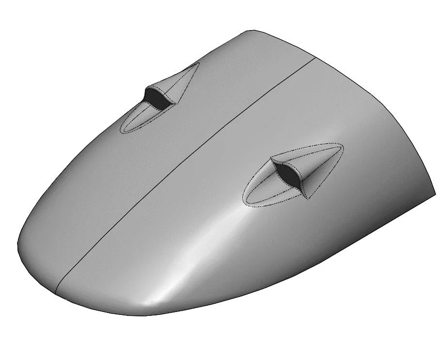
Figure 9: Example part: snowmobile hood
- I want to remove the left air scoop and leave no traces that it ever existed. To do so, I insert the Delete Face feature.
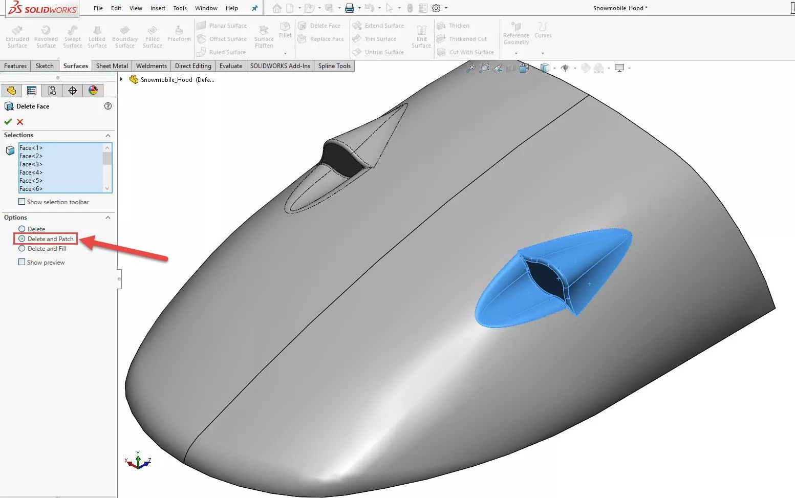
Figure 10: Inserting the ‘Delete Face’ feature and changing the function to ‘Delete and Patch’ - Most importantly, I change the option to Delete and Patch. This takes the surrounding edges and extends them. Then SOLIDWORKS will trim and knit them together all in one step.
- Ensure that ALL faces relating to the geometry are selected.
- The result is a face with no traces of the geometry.
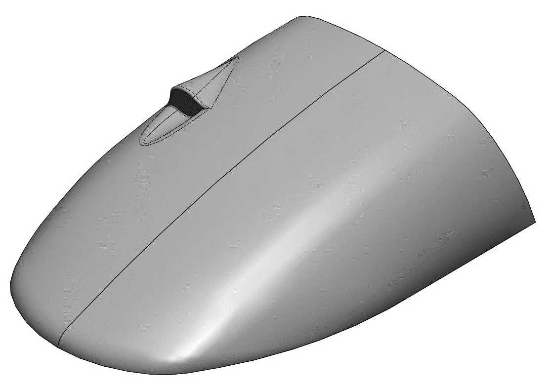
Figure 11: The face was patched with no trace of the geometry - Because this face was continuous, it was simple for SOLIDWORKS to extend the edges and knit them together. In other instances, the feature may fail because there is no logical way SOLIDWORKS can extend, trim, and knit the edges. In this case, you will need to patch the surface manually.
#3. Editing Imported Geometry: Move Face
Although the Move Face feature is not on the Surfaces tab by default, it is still a surfacing tool. This tool comes in handy when you need to modify imported geometry with no feature history.
For this example, I will use this baffle:
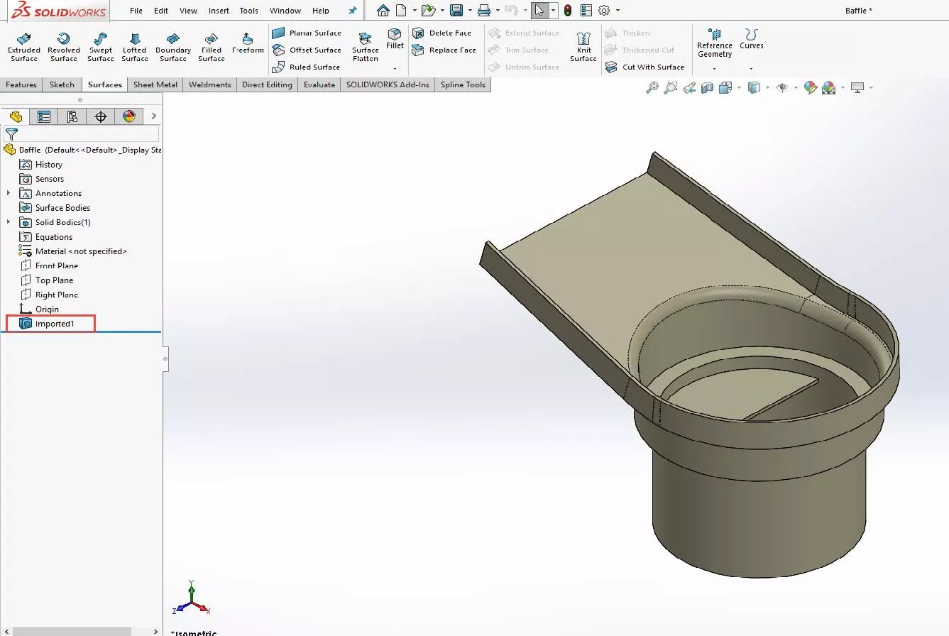
Figure 12: Example part: baffle
The only feature I have is the Imported1.
- My goal is to extend the faces of the baffle for a new fitting. To start, I will insert the Move Face command through the menu.
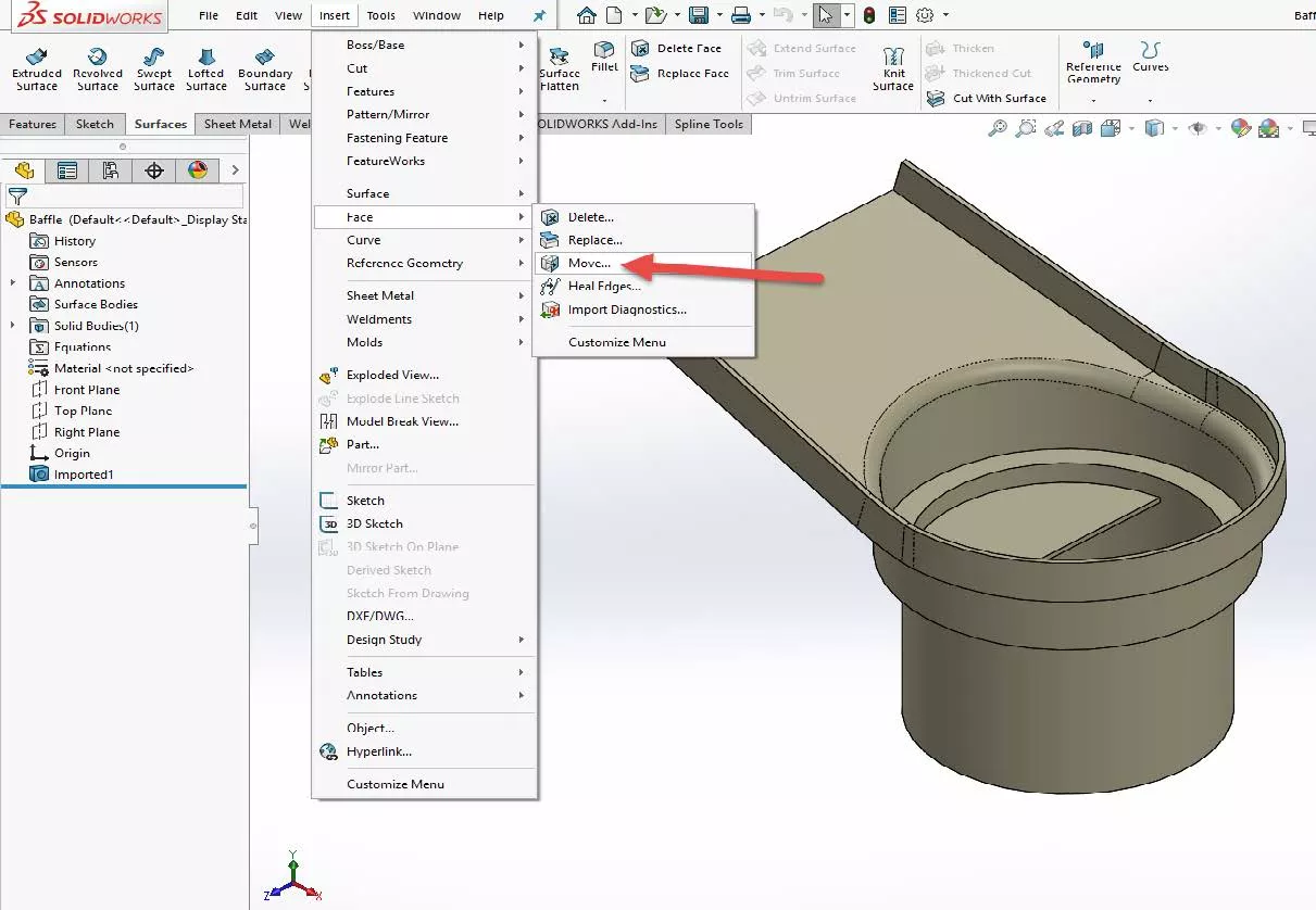
Figure 13: Inserting the ‘Move Face’ command via the ‘Insert’ menu - I then select the faces that I want to extend and set the distance to 2.00”.
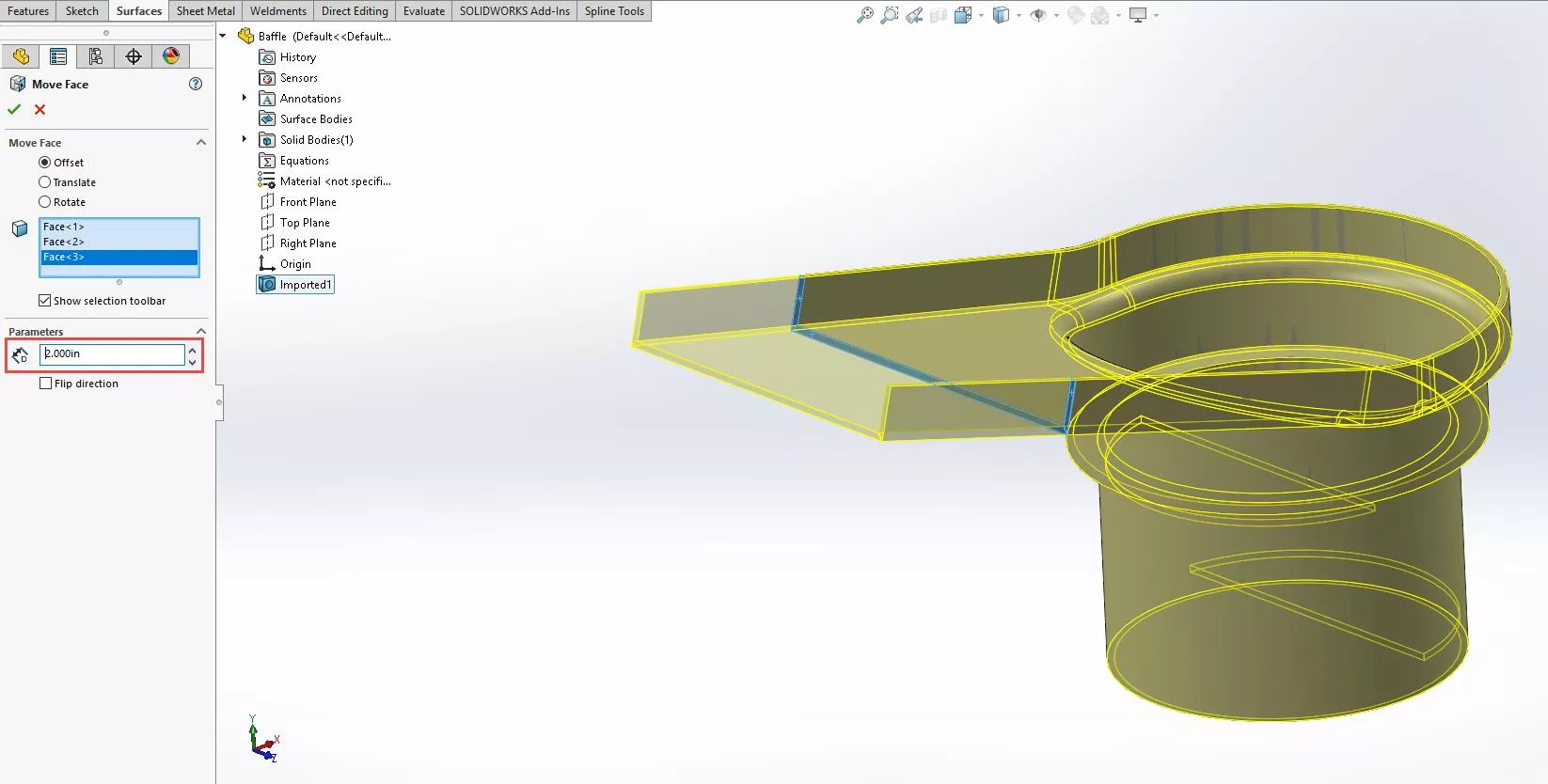
Figure 14: Inserting the ‘Move Face’ command via the ‘Insert’ menu - My result is a modified part with the beginnings of a feature tree.
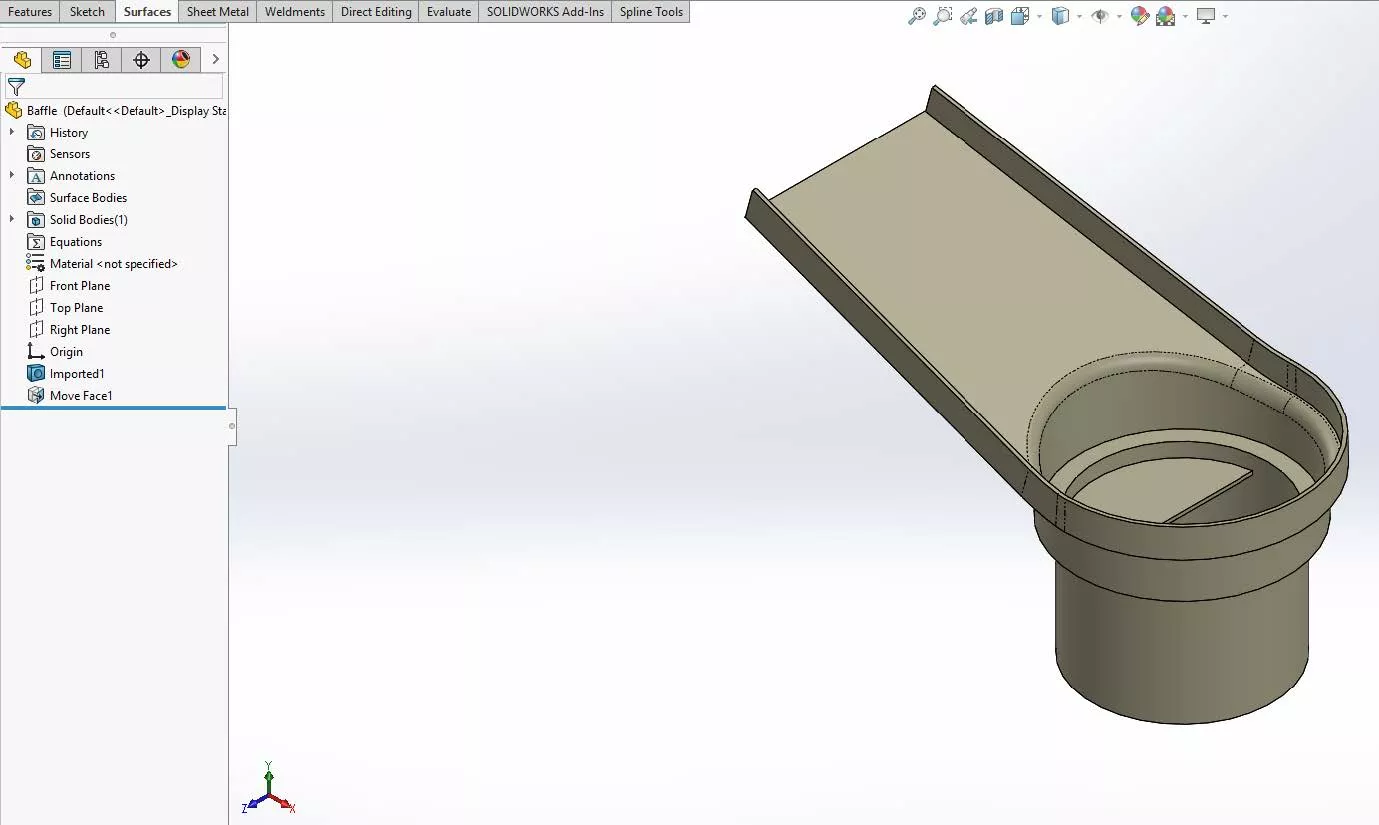
Figure 15: The desired end result
Hybrid modeling can be a very niche tool when you get stuck with solid modeling. As I mentioned before, surface modeling should be used sparingly and only when necessary, but when used appropriately, it can help solve seemingly impossible modeling tasks.
To learn more about surfacing, check out our YouTube channel and the articles listed below.
More SOLIDWORKS Tutorials
How to Use the Import Diagnostics Tool in SOLIDWORKS
How to Create an Offset Surface without Failed Faces in SOLIDWORKS
Creating a Non-circular Helix in SOLIDWORKS with Surfacing Commands
Removing External References in SOLIDWORKS Files

About Preston Ruff
Preston Ruff is a Technical Support Engineer and Certified SOLIDWORKS Instructor based out of our Headquarters in Salt Lake City, Utah. He earned a Bachelor’s degree in Manufacturing Engineering Technology from Brigham Young University and is a Certified SOLIDWORKS Expert. For many years, Preston has been passionate about CAD design, 3D printing, additive manufacturing, and being involved with STEM education. He joined the GoEngineer family in 2017.
Get our wide array of technical resources delivered right to your inbox.
Unsubscribe at any time.