3 Ways to Define a Custom Fan in SOLIDWORKS Flow Simulation
SOLIDWORKS Flow Simulation allows for the creation of custom fan conditions to emulate physical fans. This can be done in three different ways. The first method entails creating a fan curve. The other two methods allow for a more accurate representation of the fan by including additional attributes defining the physical characteristics of the fan: axial fan and radial fan.
How do I define a custom fan in SOLIDWORKS Flow Simulation?
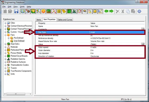
- Launch the Engineering Database (Flow Simulation, Tools, Engineering Database).
- In the ‘Database tree, expand Fans and add a new fan under the user-defined section (right-click on User Defined and select New Item).
- On the Item Properties tab, select the Fan Type from the pull-down list.
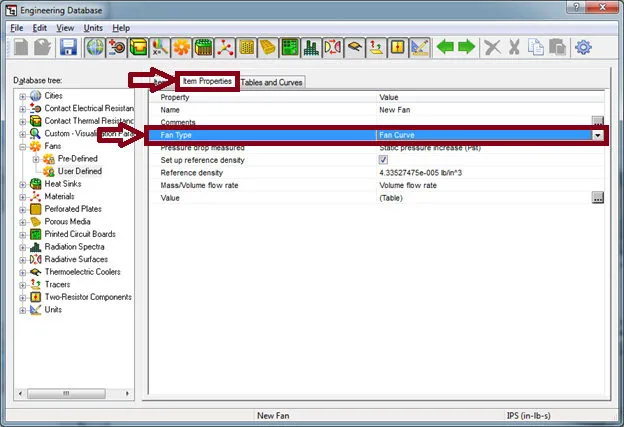
Fan Curve
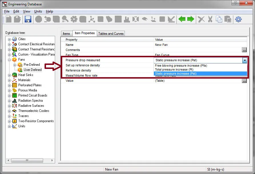
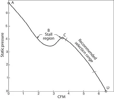
The fan curve type is a simplified representation of a physical fan. It is represented by just specifying a fan curve. This curve is defined as a dependency of the fan volume flow rate or mass flow rate on the pressure difference between the fan inlet and outlet. The pressure difference can be defined as the difference of static pressures (static pressure increase), total pressures (total pressure increase), or static pressure at the outlet, and total pressure at the inlet (free blowing pressure increase). The fan curve type does not automatically take into account swirling of the flow and must be defined manually during the insertion of the fan condition.
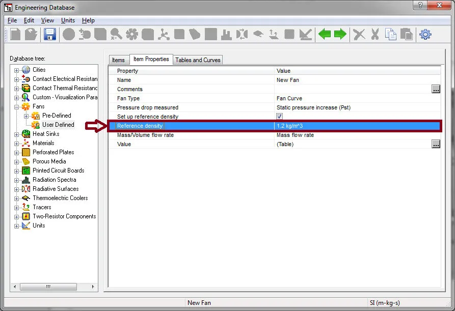
The ‘Reference Density’ option allows for modifying the default condition. The default condition implies a density value of 1.2 kg/m3, which corresponds to air at a pressure of 101325 Pa and a temperature of 20°C. When used at a different flow condition, the pressure drop produced by the fan is recalculated as ΔPcorrected = ΔP·ρ/ ρ ref, where ρ is the actual density. If the flow rate of the fan is defined as mass flow rate, it is also recalculated as mcorrected = m·ρ/ ρ ref.
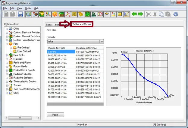
A fan curve can be inputted by navigating to the Tables and Curves tab. The data can be manually inputted or copied from another source (i.e. Microsoft Excel). To copy data into the table, select the first cell, right-click, and select Paste.
Axial Fan
The axial fan type uses the free blowing pressure increase setting for the fan curve definition. To account for swirling of the flow, the following attributes can be specified: Rotor speed, Outer diameter, Hub diameter, and Direction of rotation.
Radial Fan
For the radial fan curve, the pressure difference can be defined as the difference of static pressures (static pressure increase), total pressures (total pressure increase) or static pressure at the outlet, and total pressure at the inlet (free blowing pressure increase). To account for swirling of the flow, the following attributes can be specified:
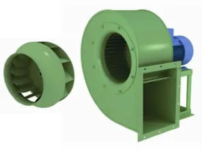
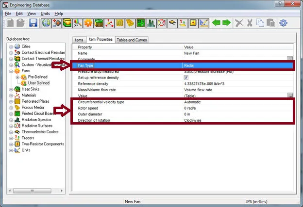
Circumferential velocity type, Rotor speed, Outer diameter, and Direction of rotation’ The circumferential velocity can be automatically calculated using the rotor speed and outer diameter or it can be manually specified.
Check out these SOLIDWORKS FLOW Simulation ARTICLES
Tank Sloshing Using SOLIDWORKS Flow Simulation
Beating COVID-19 with a Snorkel
![]()
About GoEngineer
GoEngineer delivers software, technology, and expertise that enable companies to unlock design innovation and deliver better products faster. With more than 40 years of experience and tens of thousands of customers in high tech, medical, machine design, energy and other industries, GoEngineer provides best-in-class design solutions from SOLIDWORKS CAD, Stratasys 3D printing, Creaform & Artec 3D scanning, CAMWorks, PLM, and more
Get our wide array of technical resources delivered right to your inbox.
Unsubscribe at any time.