Exploring the Design Space SOLIDWORKS Simulation Trend Tracker
Trend Tracker is a utility included in SOLIDWORKS Simulation Standard, Professional, and Premium. It enables users to track design changes dynamically when running a linear static analysis for both part and assembly models and allows for setting a design baseline. Changes can then be made to model geometry, the simulation setup, or both/and the analysis rerun. The new design iteration will be recorded and comparisons to other iterations can be made so that the best design can be achieved while exploring the design space. This guide will cover the workflow of utilizing the SOLIDWORKS Simulation Trend Tracker utility when running a linear static analysis.
![]()
![]()
Linear Static Analysis
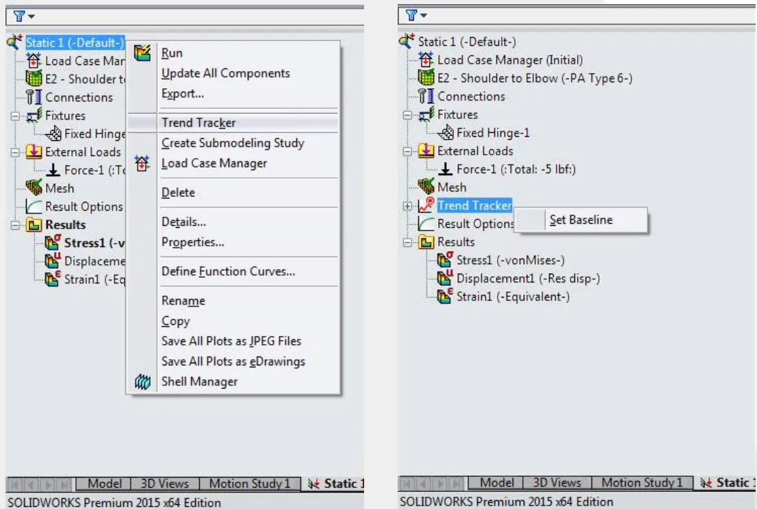
The typical workflow starts with setting up and running a linear static analysis. The study setup needs to include all relevant data such as material conditions, contact conditions if applicable, fixture and load definitions, mesh controls, etc. After the study has been run, Trend Tracker can be enabled by right-clicking at the top of the study tree and selecting Trend Tracker.
The analysis tree will update to include an additional folder for the trend tracker data. The design baseline iteration is set by right-clicking on the trend tracker folder and selecting Set Baseline.
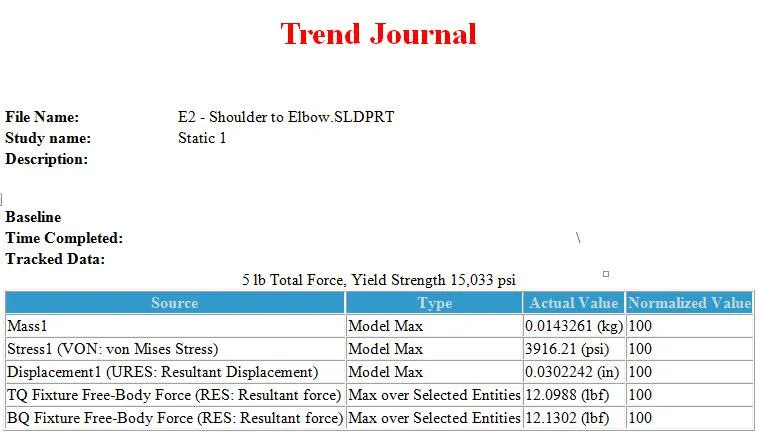
The trend journal will update with the current result data, and graphs will be created tracking the model’s mass and the maximum von Mises stress and resultant displacement. Additional graphs can be added by right-clicking on the trend tracker folder and selecting Add Tracked Data Graph…
![]()
Images of the result contour plots will also be saved. The trend tracker gallery supports the following contour plots:
- VON: von Mises stress
- P1: 1st principal stress
- P3: 3rd principal stress
- URES: Resultant displacement
- UX: Displacement (X direction)
- UY: Displacement (Y direction)
- UZ: Displacement (Z direction)
The default gallery location is …\model directory\model name - study name\Gallery.
Design Changes
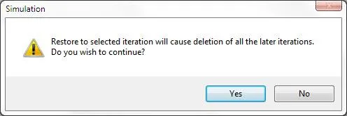
Trend Tracker iterations can record any modifications to the study setup, model geometry, or both. After the study has been rerun, a new iteration will be recorded in the trend journal, the tracked data graphs will be updated, and new result contour plot images will be saved. An individual backup copy of the model is saved for all design iterations. This allows for the model to be restored to a specific iteration and all of the iterations created after this instance will be deleted.
![]()
![]()
![]()
Benefits:
- Tracks all design changes and corresponding analysis data enabling the designer to fully explore the design space
- The model can be restored to a specific iteration
- Seamless integration into the analysis workflow
I hope you found this guide helpful. Learn more about SOLIDWORKS Simulation below.
Related SOLIDWORKS Simulation Articles
What Determines the Default Mesh Size in SOLIDWORKS Simulation?
Why Use Hex Elements in Your FEA?
3 Ways to Refresh SOLIDWORKS Simulation Plots
Show SOLIDWORKS Simulation Plots on Specific Components in an Assembly
![]()
About GoEngineer
GoEngineer delivers software, technology, and expertise that enable companies to unlock design innovation and deliver better products faster. With more than 40 years of experience and tens of thousands of customers in high tech, medical, machine design, energy and other industries, GoEngineer provides best-in-class design solutions from SOLIDWORKS CAD, Stratasys 3D printing, Creaform & Artec 3D scanning, CAMWorks, PLM, and more
Get our wide array of technical resources delivered right to your inbox.
Unsubscribe at any time.