Exporting a Deformed Body in SOLIDWORKS Simulation
The Professional and Premium versions of SOLIDWORKS Simulation allow for the creation of a solid or surface body from the deformed shape calculated in a linear static or nonlinear static study. This can be useful for manufacturing and simulation purposes.
A manufacturing example could be a formed solid plate, that is difficult to accurately model, is needed for an assembly model for interference check purposes. A nonlinear static analysis could be run, simulating the forming process and the resulting plastically deformed body could be saved and used in the assembly model.
Another use could be to run a secondary nonlinear static analysis on a deformed body in which residual stresses are not present. The functionality is available for solid, shell, and mixed mesh studies for both part and assembly models. It is not available for studies including sheet metal bodies and solid bodies meshed using beam elements. This document will cover how to export a deformed body from SOLIDWORKS Simulation.
Linear Static Analysis
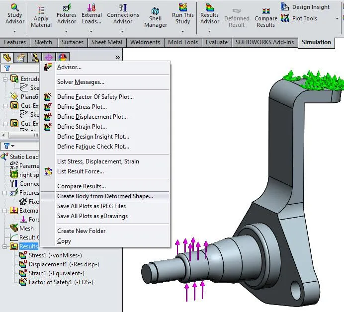
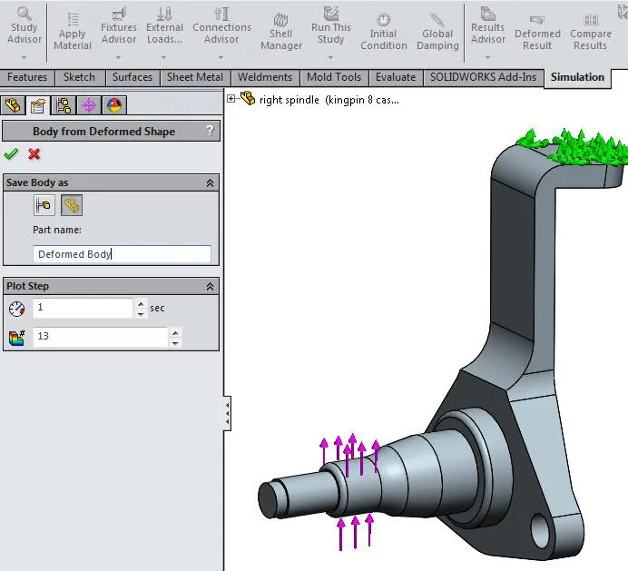
To export a deformed body, right-click on the results folder in the Simulation study tree and select “Create Body from Deformed Shape…”
You can specify the option to create the body as a new configuration or save it as a new part document in the location of the active document.
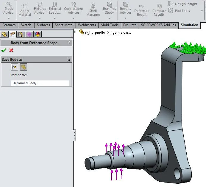
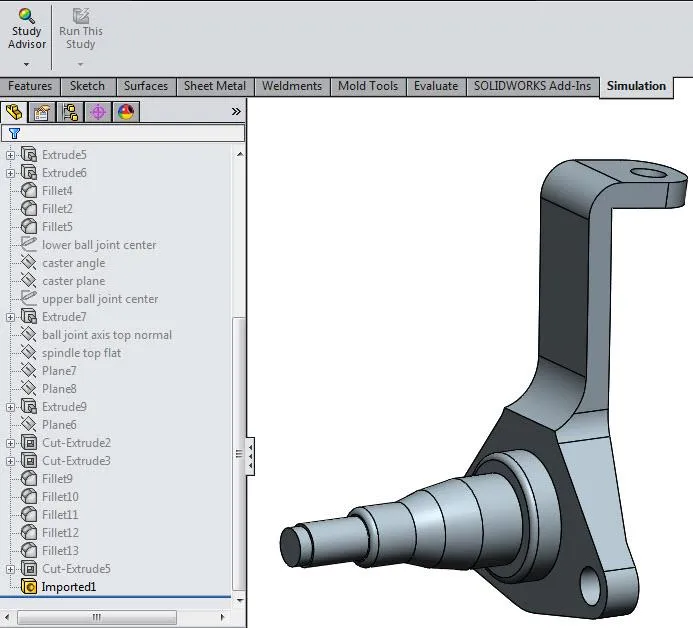
The deformed body is saved as an imported solid body with no feature history or external references. If the analysis is rerun with a different boundary condition setup or with updated model geometry, the deformed body will not update. A new deformed body will have to be exported to reflect the updated results. If the new configuration option is used, a new configuration is created with the original part model features suppressed and a new imported feature is inserted at the end of the feature manager design tree.
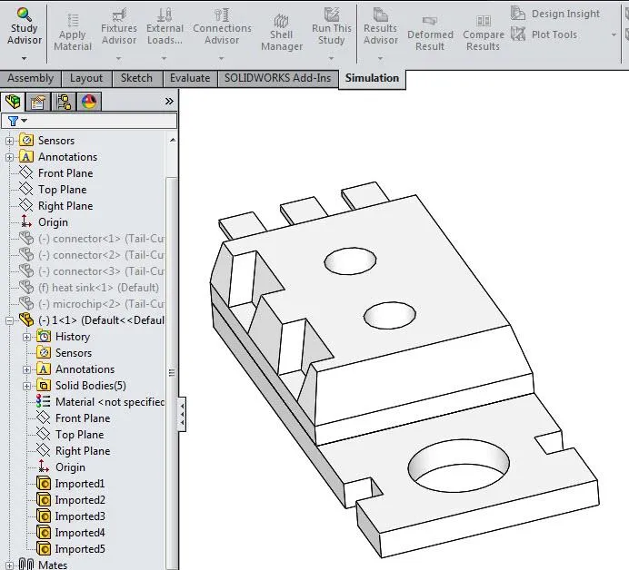
For an assembly analysis, the resulting deformed body is saved as a multi-body part. If the configuration option is selected, a multi-body part is saved and added to a new assembly configuration. Both the part and configuration share the same specified name. The original assembly components are suppressed in the new configuration.
Nonlinear Static Analysis
The deformed body is exported using the same process. The difference is that a plot step can be specified for the export. If a loading condition is specified using a user defined time curve, then the deformed body could be saved out at specified load increments. For instance, the deformed shape could be exported after half the load is applied.
Troubleshooting
Error Creating Deformed Body
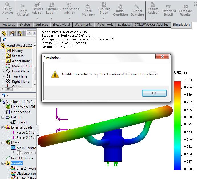
Two potential issues may arise during the creation of a deformed body. The first issue is when an error message appears after selecting the green checkmark to create the deformed body.
Error: Unable to sew faces together. Creation of deformed body failed.
The error message usually appears due to an ill-defined mesh. The mesh is too coarse to capture the geometry correctly in the deformed state. The resolution to the issue is to rerun the analysis with a more refined mesh and retry saving the deformed body.
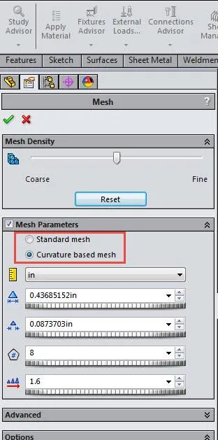
To complicate things, the error message may pop up when working with a good mesh, but created using the “Standard mesh” option. The failure seems to occur when the deformation levels go beyond small displacements. The “Curvature based mesh” option has been very consistent with saving a deformed body. When the process fails due to a poorly resolved mesh, adjusting the auto mesher settings and/or applying additional mesh controls to refine the mesh usually resolves the problem.
Resulting Deformed Body Does Not Match Result Output
The second potential issue that may arise during the creation of a deformed body is the resolution of the deformed body saved from the analysis results. When the deformed body is opened in SOLIDWORKS, some surfaces may be missing or highly distorted. The process the software uses to create the deformed body is listed below.
When the deformed shape of the model is exported, the software creates a cloud of points with a standard number of locations coming from deformed node locations to represent each surface in the model. From the cloud of points, the deformed surface geometry is then created.
For complex surfaces, the number of points is too small to correctly represent the shape of the surface. A workaround is to split the complex surfaces into a subset of smaller simpler surfaces and rerun the analysis. The resulting deformed body should then have a better surface resolution.
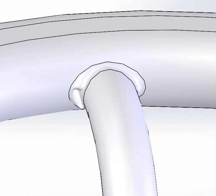
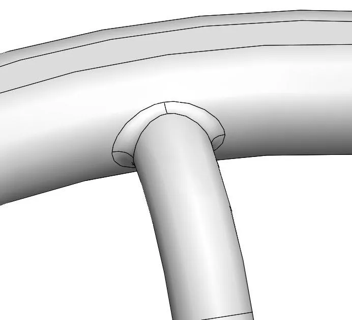
The images below depict the original and deformed bodies of a hand wheel. The filleted surfaces where the spokes meet up with the rim were highly distorted in the deformed body. Solving the analysis with a more refined mesh along the surfaces did not resolve the export issue.
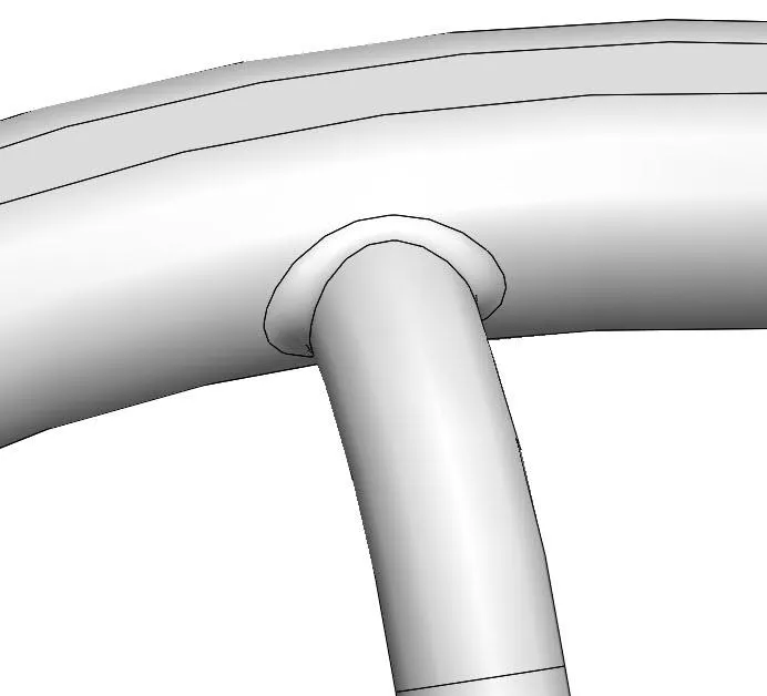
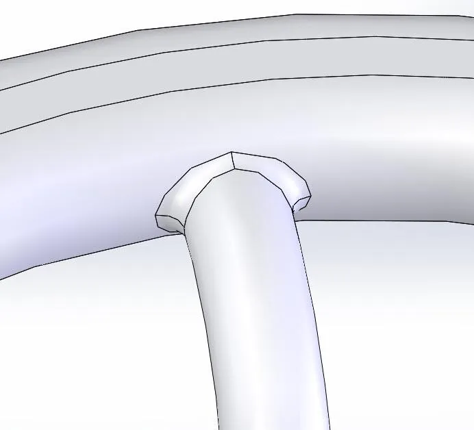
The deformed body export problem was resolved by using the SOLIDWORKS split line feature to break up each surface into four separate simpler surfaces. The images below depict the updated hand wheel’s original and deformed bodies.
Best Practices for Exporting a Deformed Body in SOLIDWORKS Simulation
- Use the SOLIDWORKS split line feature to break up complex surfaces into smaller simpler surfaces
- Use the curvature based mesh option
- Add mesh controls to resolve the mesh in areas where high strains are expected
Expand Your SOLIDWORKS Simulation Skillset
7 Steps to Perform a Fatigue Analysis
Performing a Thermal Analysis in SOLIDWORKS Simulation
Troubleshooting SOLIDWORKS Simulation No Penetration Contact Sets Recommendations
![]()
About GoEngineer
GoEngineer delivers software, technology, and expertise that enable companies to unlock design innovation and deliver better products faster. With more than 40 years of experience and tens of thousands of customers in high tech, medical, machine design, energy and other industries, GoEngineer provides best-in-class design solutions from SOLIDWORKS CAD, Stratasys 3D printing, Creaform & Artec 3D scanning, CAMWorks, PLM, and more
Get our wide array of technical resources delivered right to your inbox.
Unsubscribe at any time.