Troubleshooting SOLIDWORKS Simulation No Penetration Contact Sets Recommendations
At some point, a SOLIDWORKS Simulation user comes across a study that will not solve because there is something wrong with the no penetration contact sets that they have set up. In this article, I cover some of the investigative troubleshooting methods to employ when you suspect one or more no penetration contact sets in the analysis setup is incorrect and something needs to be changed for the study to be solved.
This list is meant to give some of the most useful and often used solutions to fix problems with no penetration contact sets. However, these are not all of the possible solutions.
#1: Geometry Suggestions
Simplify the analysis. Exclude all unnecessary bodies and features.
Use the Split Line command to localize contact areas. Only include the areas necessary for contact.
![]()
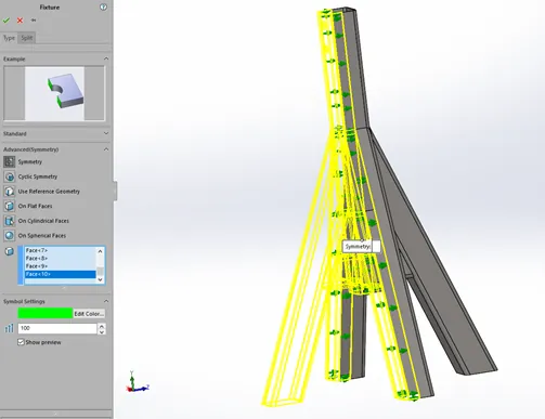
Use the symmetry fixture tools whenever possible to their maximum extent (e.g., use two symmetry plans when possible instead of just one).
Check for connections where they should not be due to misused Global or Component no penetration contact sets. Especially on large and complex assemblies.
#2: Fixtures and Loads
Add additional fixtures if needed to improve stability (e.g., add an “artificial fixture” to a vertex and restrain one or more degrees of freedom).
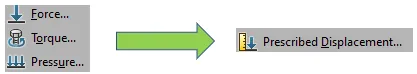
Simplify or suppress some loads while troubleshooting. Try experimentally to add a prescribed displacement instead of a force or pressure load to stabilize the model since displacement inputs tend to be more stable than force or pressure load inputs.
#3: Mesh
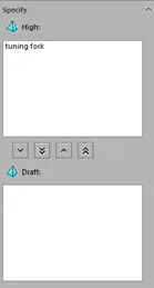
Change the mesh to a coarse, Draft Quality element type mesh to see if this simplification will allow the simulation to run.
When a coarse Draft Quality mesh works, gradually add mesh controls to areas of high interest and test run again.
![]()
When the results look reasonable and what is expected, switch to High-Quality Elements and run a full mesh convergence analysis.
Mesh the No Penetration Contact Set Source or Set 1 box more densely than the Target or Set 2 box.
#4: Miscellaneous Settings and Properties
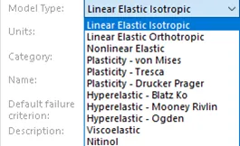
If another material model type is not working as an experiment, use the Linear Elastic Isotropic material model for all part files in the assembly.
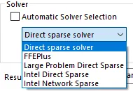
Make sure the Direct Sparse solver is being used.
Try suppressing in groups all contact sets. Widdle them down to the one or more contact sets that are causing the issues. Then suppress these contacts and run again to gauge the stability of the model. Are these contacts necessary? If they are, how can they be changed or replaced to gain the needed effect?
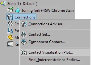
Use the Contact Visualization Plot to visually see if all the contact sets that need to be present are and if they are in the correct locations.
I hope you found this article helpful. Check out more SOLIDWORKS Simulation tips and tricks below.
Expand your SOLIDWORKS Simulation Skillset
SOLIDWORKS Simulation Tips: No Penetration Contact Set Setup

About Taran Packer
Taran is a SOLIDWORKS Simulation Technical Support Specialist at GoEngineer. He has a Bachelor’s degree in Biomedical Engineering from the University of Utah. Taran enjoys learning about different tools in SOLIDWORKS Simulation, Flow Simulation, and Plastics.
Get our wide array of technical resources delivered right to your inbox.
Unsubscribe at any time.