Flip Plane Normal in SOLIDWORKS
If you have utilized SOLIDWORKS Reference Geometry (planes, axes, coordinate systems, etc.), you may have once thought to yourself, why do I have two ‘Normal to’ icons when I right click my reference plane in the Feature Tree? (see Figure 1)
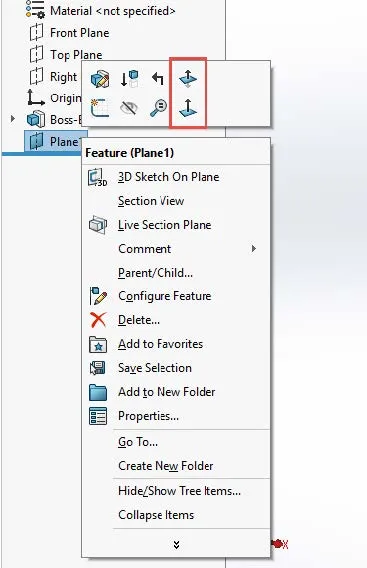
Figure 1. The ‘Flip Normal’ (top) and the ‘Normal to’ (bottom) commands in the right-click menu
The truth is, these commands are quite different. You are familiar with the standard ‘Normal to’ command:

Figure 2. The ‘Normal to’ command
But this icon is the ‘Flip Normal’ command:

Figure 3. The ‘Flip Normal’ command
This command reverses the normal of the plane to the opposite side. In SOLIDWORKS, every reference plane has one side that is designated as the primary normal. All sketches on the primary normal have a right and a left. Technically, every plane has two normals—one on each side, but just as with a piece of paper, if we sketch something on one side and we view it from the opposite side, the shapes are reversed. To better understand how this works in SOLIDWORKS, consider this example:
We have a part with a simple boss:
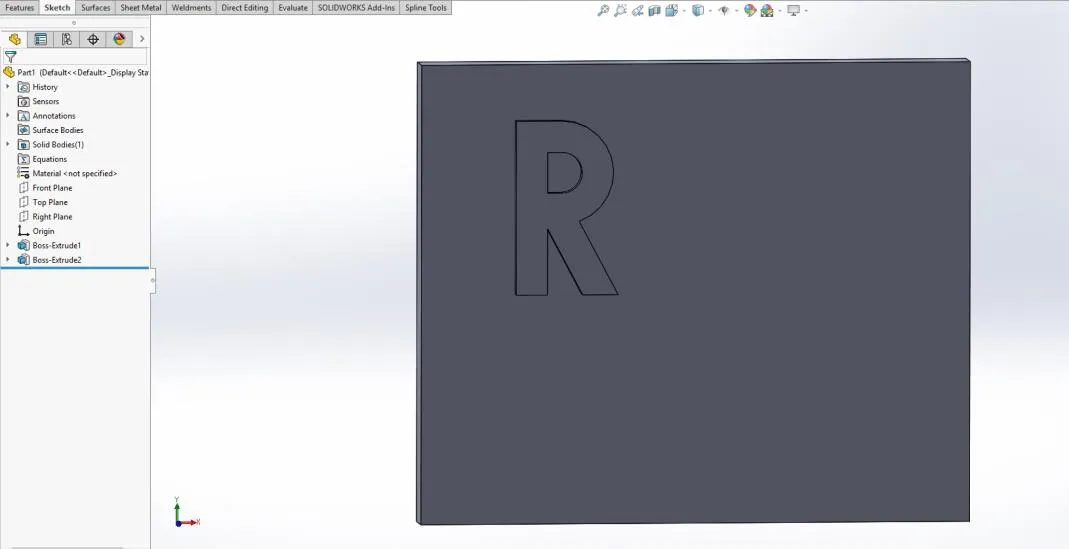
Figure 4. Two simple extrudes
(FYI this ‘R’ was created with lines and arcs. Sketched text cannot be copied.)
Let’s say we did the following:
- Add a reference plane (Plane1) offset from the front face of Boss-Extrude1 square extrude.
- Edit the absorbed sketch of Boss-Extrude2, drag-select all entities in the sketch, and hit Ctrl+C (or Edit, Copy).
- Select the reference plane Plane1, start a new sketch, then hit Ctrl+V (or Edit, Paste).
- Exit the sketch.
This is what we should have:
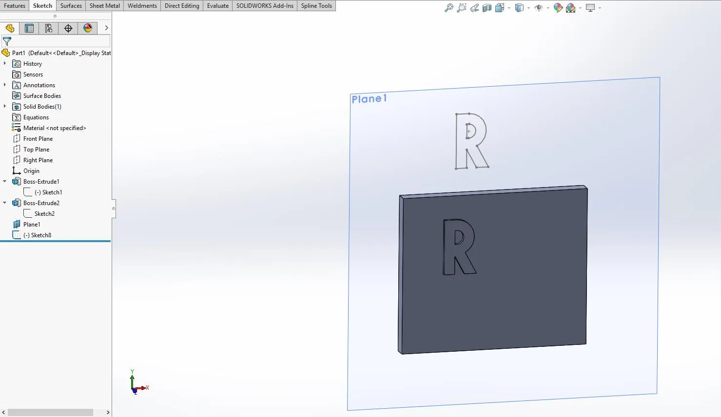
Figure 5. Copied sketch on reference plane Plane1
To us, this ‘R’ looks correct. The arcs of the ‘R’ are on our right as we look at it from the front view. Notice that the reference plane’s name (Plane1) is at the top-left of the plane. This means that we are looking at the primary normal or the “front” of the plane.
Now I will invoke the ‘Flip Normal’ command by right-clicking the reference plane Plane1 and selecting the ‘Flip Normal’ icon. If we remain on the front view, this is now what we will see:
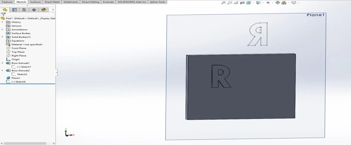
Figure 6. The normal flipped on Plane1
Notice that the arcs of the ‘R’ are now on our left as we look at it from the front. Another interesting note: the name of the reference plane (Plane1) is now at the top-right of the plane. This means we are now looking at the secondary normal or the “back” of the plane. If we view this sketch from the back view we see this:
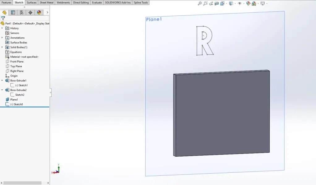
Figure 7. View from the back
From the back view, the ‘R’ looks correctly oriented. The arcs are on our right. The ‘Flip Normal’ command flipped Plane1 to the opposite side. Think of it as flipping over a piece of paper to the opposite side. All sketches created on the front of the paper will look backwards to us when we flip the paper and look at the opposite side.
Hopefully, this cleared up the common misunderstanding of the ‘Flip Normal’ command. If this confused you further, a simple trick should help:
- Hold up your left hand with your pointer finger and thumb in the shape of the letter ‘L’ next to the monitor. This is your left, and it will always be your left, no matter how the part or assembly is rotated.
- When you look at a reference plane, if the name of the plane is in the top-left corner, you are looking at the primary normal, meaning all sketches will be oriented left-to-right according to your hand. If the name is in the top-right corner, you are looking at the secondary normal, and if you paste a sketch, it will look backward. You will need to flip the normal of the plane using the ‘Flip Normal’ command.
Remember, a plane is like a piece of paper. Happy modeling!
Did you enjoy this SOLIDWORKS tutorial? Be sure to subscribe!
More Articles We think You'll like
Frequency Study Plot with SOLIDWORKS Simulation
![]()
About GoEngineer
GoEngineer delivers software, technology, and expertise that enable companies to unlock design innovation and deliver better products faster. With more than 40 years of experience and tens of thousands of customers in high tech, medical, machine design, energy and other industries, GoEngineer provides best-in-class design solutions from SOLIDWORKS CAD, Stratasys 3D printing, Creaform & Artec 3D scanning, CAMWorks, PLM, and more
Get our wide array of technical resources delivered right to your inbox.
Unsubscribe at any time.