How to Minimize Sink Marks in Ribs in SOLIDWORKS Plastics
Shrinkage in a real molded component is observed by actual depressions in the mold, as shown in Figure 1. After the injecting and packing of the plastic into the mold, during the cooling process, the plastic material undergoes a volume reduction. In sections that are too thick, the plastic on the surface cools faster than the plastic in the thick section, which results in the part caving in at the thick location and forming a sink mark. These depressions can be small or large, but either way are usually very noticeable since the light reflects in a different direction on this surface of the part than other areas of the component.
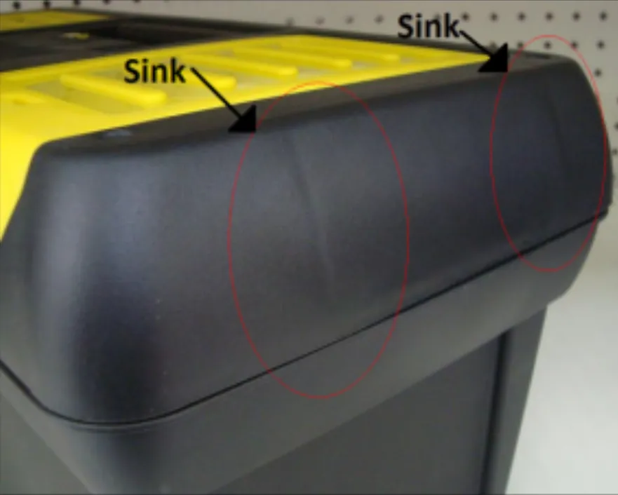
Figure 1: Obvious sink marks in an injection molded product
The sink mark prediction tool in SOLIDWORKS Plastics is a potent tool in predicting sink mark locations and how deep the sink mark will end up being. In this article, I will show how to find and reduce sink marks that tend to form in injection molds at rib locations.
After performing a flow analysis in SOLIDWORKS Plastics, the user can select the sink mark predictor tool by clicking on the Sink Marks entry (see Figure 2).
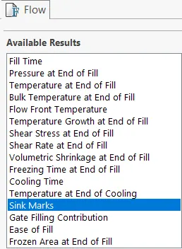
Figure 2: Sink Mark Prediction tool
In the image seen in Figure 3, the sink mark predictor in SOLIDWORKS Plastics shows a significant sink mark will form on the left rib, but almost no sink mark will form on the right rib of this simple part I mocked up in SOLIDWORKS. The sink mark contours are colored by the depth of shrinkage away from the mold.
The more significant the shrinking happening in any given area, the redder the color. Blue indicates locations with close to zero shrinkage.
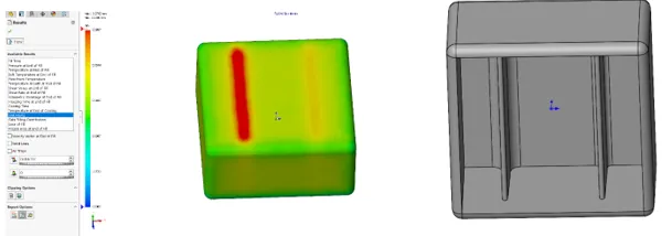
Figure 3: Left side: SOLIDWORKS Plastics Analysis. Right side: SOLIDWORKS 3D CAD model
When looking at a section view of the SOLIDWORKS model, I’ve added the blue circles, in Figure 4, to show the locations of the rib root thickness in the part wall. The rib root thickness depends on the rib thickness at the base of the rib, as well as the fillet radius also at the bottom of the rib. Due to the nature of adding ribs, these locations are unavoidably thicker than the areas where there is no rib and can contribute to sink marks.
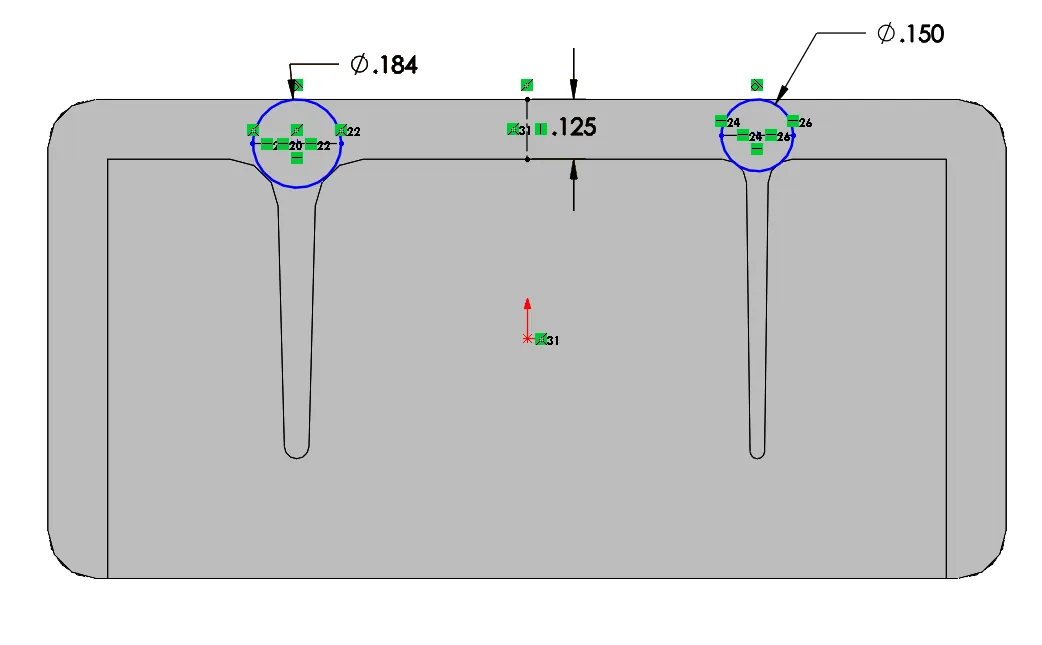
Figure 4: SOLIDWORKS Model Section View
To cool the rib location evenly and avoid sink marks in an injection molded part, it is best practice not to allow the rib root thickness diameter to get too large. Some design guidelines to avoid sink marks are as follows:
- The base thickness of the rib should fall in the range of ½ to 2/3 of the attached parent wall thickness.
- The rib fillet radius should fall in the range of ¼ to ¾ of the parent wall thickness.
- Since the Rib Thickness and Rib Fillet together make the Rib Root Thickness, these two variables added together should not exceed a diameter that is over 125% of the parent wall thickness.
- The draft angle of ribs should fall in the range of 1.5 to 2 degrees per inch of the rib length not to minimize sink marks but to facilitate part ejection.
According to these guidelines, the reason why Plastic Analysis is predicting a sink mark in the thicker rib to the left, and not in the thinner rib to the right, is that the wall thickness is 0.125” while the thick rib root thickness, on the left, is 0.184”, or 147% of the wall thickness, versus the thin rib root thickness, on the right, is 0.15”, or 120% of the part wall thickness.
If these guild lines are followed, the injection mold designer can be confident that his part will come out of the mold with minimal sink marks at the locations of the ribs. Still, it is also always good to simulate the injection molding process and obtain an estimate of the sink mark from a program like SOLIDWORKS Plastics before creating a mold. This can significantly reduce the cost and increase your confidence in the final product.
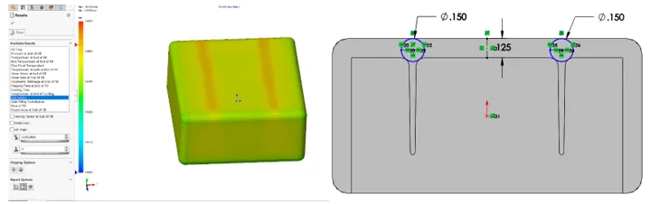
Figure 5: Left side: SOLIDWORKS Plastics Analysis with no sink marks present Right side: SOLIDWORKS 3D CAD model following the correct rib creation guidelines
I hope you found this tutorial for minimizing sink marks in ribs helpful. Enjoy more SOLIDWORKS Plastics tutorials by clicking the links below.
SOLIDWORKS Plastic Tutorials
Symmetric Runners in SOLIDWORKS Plastics
Using SOLIDWORKS Plastics to Design Plastic Sample Kits | Customer Story

About Taran Packer
Taran is a SOLIDWORKS Simulation Technical Support Specialist at GoEngineer. He has a Bachelor’s degree in Biomedical Engineering from the University of Utah. Taran enjoys learning about different tools in SOLIDWORKS Simulation, Flow Simulation, and Plastics.
Get our wide array of technical resources delivered right to your inbox.
Unsubscribe at any time.