Symmetric Runners in SOLIDWORKS Plastics

Article by GoEngineer on Apr 06, 2017

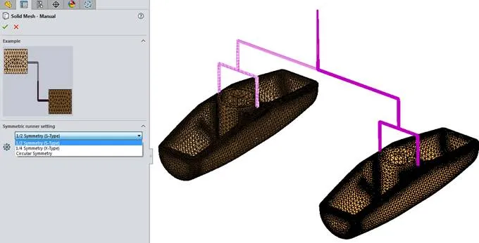
SOLIDWORKS Plastics 2015 introduced the capability of analyzing a model using a symmetric runner.  This capability is available in SOLIDWORKS Plastics Professional and SOLIDWORKS Plastics Premium.  It can used to reduce a multi-cavity mold with a symmetric runner system to a single cavity analysis.  The multi-cavity mold has to be symmetric about a plane or two planes of symmetry, or an axis (for circular symmetry).  Analyzing a model using symmetry allows for a quicker computation as compared to analyzing the entire system.  Also, the user has the ability to apply a more refined mesh on the reduced model to obtain more resolved results and still solve the analysis in a timely fashion.

SOLIDWORKS Model Setup

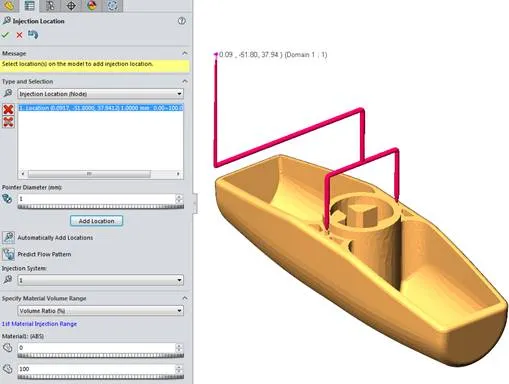
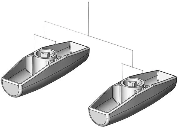
Original multi-cavity mold model is shown below with runner system layout sketch.

SOLIDWORKS Plastics Symmetric Runner original multi-cavity mold model

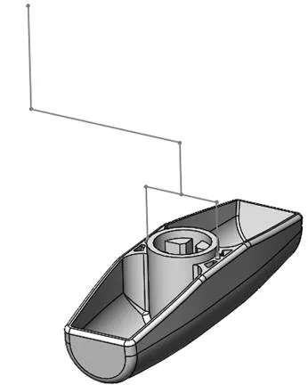
The first step is to create a SOLIDWORKS configuration including a single cavity and half of the runner layout sketch.

SOLIDWORKS Plastics Symmetric Runner create a SOLIDWORKS configuration including a single cavity and half of the runner layout sketch

SOLIDWORKS Plastics Setup

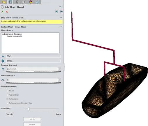
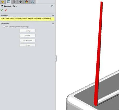
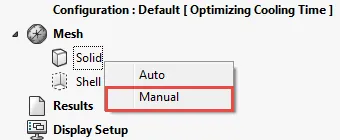
Setting up a symmetrical runner requires the manual creation of a solid mesh and virtual runner system.

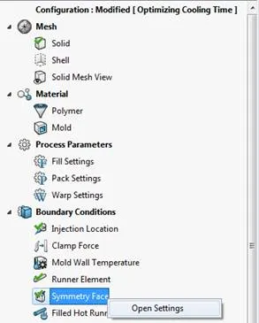
Right-click on the Solid link under the Mesh section and select the Manual option.

Right-click on the Solid link under the Mesh section

On the first screen of the solid mesh creation dialog window, check on the Runner and Cooling System Design option and select the next arrow.

SOLIDWORKS Plastics Symmetric Runner  check on the Runner and Cooling System Design option

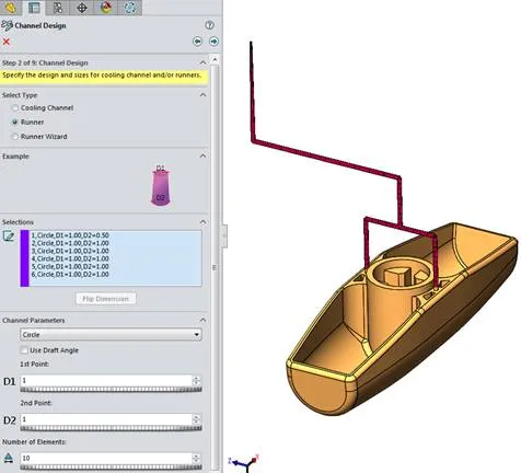
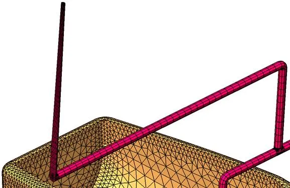
On the Channel Design page, select Runner and then define the runner segments using the runner layout sketch.

SOLIDWORKS Plastics Symmetric Runner select Runner and then define the runner segments

Create the surface mesh.

SOLIDWORKS Plastics Symmetric Runner Create the surface mesh

Specify the solid mesh type as Tetrahedral.  The Hexahedral solid mesh type does not allow for a symmetrical runner setup.

SOLIDWORKS Plastics Symmetric Runner Specify the solid mesh type as Tetrahedral

On the next screen, check on the option for Symmetrical runner and select the Edit button.

SOLIDWORKS Plastics Symmetric Runner check on the option for Symmetrical runner and select the Edit button

Next, specify the Symmetric runner setting.  There are three available options (1/2 Symmetry, 1/4 Symmetry and Circular Symmetry).

SOLIDWORKS Plastics Symmetric Runner Next, specify the Symmetric runner setting

The resulting mesh displays the runner meshed with solid elements and depicts the specified symmetry type (in this example, 1/2 symmetry).

SOLIDWORKS Plastics Symmetric Runner the resulting mesh displays the runner meshed with solid elements

Within the SOLIDWORKS Plastics project tree, the software automatically defines a Symmetry Face boundary condition.

SOLIDWORKS Plastics Symmetric Runner the software automatically defines a Symmetry Face boundary condition

Within the Symmetry Face dialog window, the software automatically selected all of the appropriate element faces for the symmetric runner setup.

SOLIDWORKS Plastics Symmetric Runner within the symmetry face dialog window

Define the Injection Location and then run the analysis.

SOLIDWORKS Plastics Symmetric Runner define injection location
 

About GoEngineer

GoEngineer delivers software, technology and expertise that enable companies to unlock design innovation and deliver better products faster. With more than 35 years' experience and tens of thousands of customers in high tech, medical, machine design, energy and other industries, GoEngineer provides best-in-class design solutions from SOLIDWORKS CAD, Stratasys 3D printing, Creaform & Artec 3D scanning, CAMWorks, PLM, and more

View all posts by GoEngineer