SOLIDWORKS Simulation Tips: No Penetration Contact Set Setup
In our SOLIDWORKS Simulation Professional course, I usually get a lot of questions from students when discussing No Penetration Contact Sets and how to set them up correctly. In this article, I'll answer those frequently asked questions and offer tips for no penetration contact setup in SOLIDWORKS Simulation.
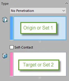
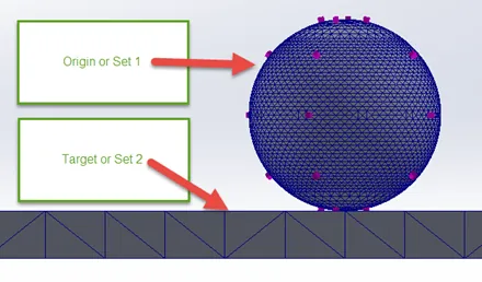
In the local manual Contact Set option in SOLIDWORKS Simulation, there are two boxes under Type; one blue and one pink. The top blue box is generally called the Origin or Set 1, while the bottom pink box is called either the Target or Set 2 interchangeably. In these boxes, the SOLIDWORKS Simulation user places geometry faces, edges, or vertices to tell the program that the two geometric units are to be allowed to deform each other when pressed together.
When creating local No Penetration Contact Sets manually, the simulation user can, in theory, select any vertex, edge, or face for the source contact and any face for the target contact. SOLIDWORKS Simulation works better, however, when the below best practices are adhered to.

No Penetration Geometry Selection Recommendations
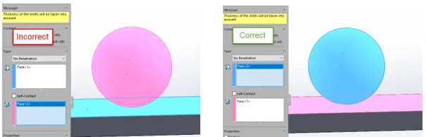
- A target face should be flatter and larger than the source face(s).
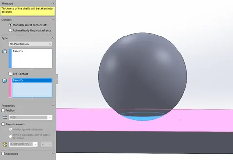
- Before the analysis starts, the position of the faces of the part files chosen for the No Penetration Contact Set should not be separated by a gap but should be touching. This is especially important when the driving load is a force or pressure.

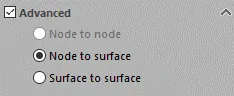
- The choice for which geometric face, edge, or vertex goes in which box has to do with the geometry and the mesh. For a No Penetration Contact set with a node to node contact condition, it does not matter what type of face goes in the Origin or Set 1 or Target or Set 2 boxes. But for all other contact conditions involving either node to surface or surface to surface contact conditions, the choices between which geometry goes in the Origin or Set 1 box or Target or Set 2 box is important.
- For node to node and surface to node options, the Source or Set 1 entities can be a vertex, edge, or surface. But when using the Surface to Surface option, the Source or Set 1 entity can only be faces. The Target or Set 2 entity can always only be faces.
- Origin or Set 1 face(s) should be meshed finer than Target or Set 2 face(s). Not doing this will create reduced accuracy in the local area that the No Penetration Contact set is defined in. This inaccuracy is especially true when using the Node to Surface contact option.
- The friction option only increases the computational intensity of each No Penetration Contact set so it is recommended to leave this option turned off unless it is required to stabilize your model and you know for sure what the exact Friction Coefficient is used in the specific situation that is being simulated.
- No Penetration Contact sets are computationally intensive so the fewer that are created while maintaining as close to real-life conditions the better. Having multiple faces in the Origin or Set 1 and Target or Set 2 boxes with fewer overall No Penetration Contact sets is better than having more contact sets with one face pair per No Penetration Contact set.
- Where this face grouping option is utilized, it is best to make sure that a full group in either the source or Set 1 or Target or Set 2 boxes makes geometric sense grouped. For instance, continuous faces on one part file touching another part file.
- The 'Automatically find contact sets' option makes the creation of No Penetration Contact sets much easier but it is not always a good idea since it always only creates face pairs with long lists of contact sets instead of grouping faces together.
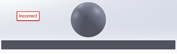
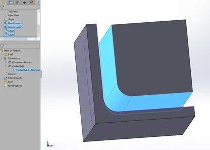
- When grouping faces onto a single Origin or Set 1 box or Target or Set 2 boxes in the No Penetration Contact set, this should not be considered an option when there is a 90-degree angle to the faces that are touching or are expected to touch during the analysis. In these cases, create two No Penetration Contact sets or place a large round fillet in the sharp corners then place the three faces including the fillet into the Origin or Set 1 or Target or Set 2 boxes as shown below.

Two Contacts with corner geometry above vs one contact with a filleted corner below
- Putting split lines on the Origin or Set 1 face(s) to make them smaller to better match the area that is or will come in contact with the Target or Set 2 faces during the analysis will reduce the studies' complexity and increase the analysis speed. Placing a split line on target or set 2 faces has no effect on analysis speed one way or the other.
- While simulation studies will run when the Origin or Set 1 face in one contact set is used as a Target or Set 2 faces in another contact set, it is not recommended because in complex models it may lead to contact failure which will prematurely stop the analysis.
I hope you found this Simulation tutorial helpful. For more SOLIDWORKS Simulation tips and tricks, check out the links below.
SOLIDWORKS Simulation Tutorials

About Taran Packer
Taran is a SOLIDWORKS Simulation Technical Support Specialist at GoEngineer. He has a Bachelor’s degree in Biomedical Engineering from the University of Utah. Taran enjoys learning about different tools in SOLIDWORKS Simulation, Flow Simulation, and Plastics.
Get our wide array of technical resources delivered right to your inbox.
Unsubscribe at any time.