Piecewise Nonuniform Pressure in SOLIDWORKS Simulation
In this article, we will illustrate one method of setting up one of the most complex load patterns SOLIDWORKS Simulation has available: a piecewise non-uniform pressure distribution. Also, a comparison to an alternative method using split lines will be discussed near the end of the article.
Model and setup
Todd Parker, a member of the EAA (Experimental Aircraft Association), modeled the airfoil shown in figure 1 using SOLIDWORKS.
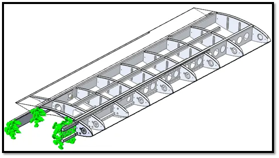
Figure 1 - CAD model created in SOLIDWORKS by Todd Parker
To simulate the structural deformation, Todd wanted to import some pressure information he had obtained from his calculations. He placed these calculations in Microsoft Excel and did some curve fitting to see what these loads might look like along the chord of the wing on both its top and bottom surfaces (figure 2).
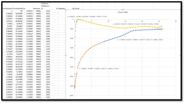
Figure 2 - Piecewise non-uniform pressure load we want to use for a Simulation
How do we enter each of these equations into SOLIDWORKS Simulation?
SOLIDWORKS Simulation Functions
One method of inputting Todd’s equations into SOLIDWORKS is to use some of the SOLIDWORKS Simulation built-in functions to create a piecewise equation. Usually functions like STEP or BOXCAR would do the trick, but these are not available (as of SOLIDWORKS 2020; see figure 3).
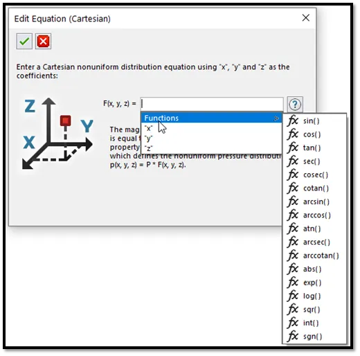
Figure 3 - SOLIDWORKS Simulation non-uniform load functions
However, one of these functions can be exploited to create a piecewise function.1 If we run a test with the int() function, this seems like it's close to a STEP function we are looking for (figure 4).
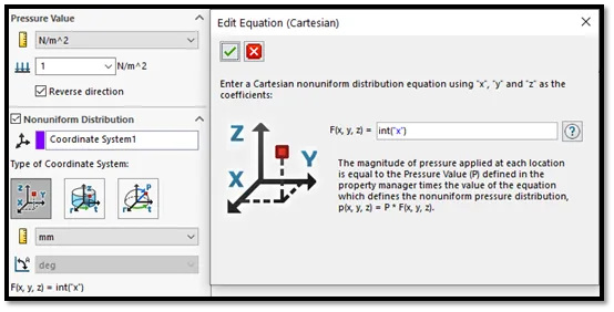
Figure 4 - int() function looks a bit like a STEP function.
And if we focus on one region in particular (figure 5), this will be the region of the int() function we can use to turn loads on and off.
Figure 5 - This is the type of function that should work for creating a piecewise function.
We can create equations that convert this region into STEP and BOXCAR functions (figure 6). With our STEP and BOXCAR equations, we are ready to construct a piecewise nonuniform pressure with Todd’s spreadsheet curves.
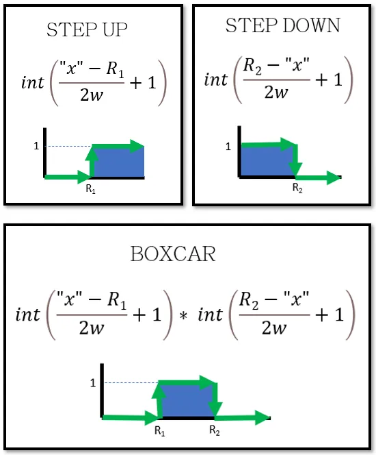
Figure 6 - int() function converted to STEP and BOXCAR
The values in the equations represent the following:
“x”: This is the coordinates of the pressure. X, Y, and/or Z can be used if cartesian is selected.
R1: The function will evaluate to zero when “x” is less than R1 and it will evaluate to one when “x” is greater than R1. This is used for “stepping up” or “turning on” a function beyond a certain value of “x”.
R2: The function will evaluate to one when “x” is less than R2 and it will evaluate to zero when “x” is greater than R2. This is used for “stepping down” or “turning off” a function beyond a certain value of “x”.
w: This is your largest estimate for the overall length of the face in the “x” direction. This keeps the int() function from going beyond its intended domain so make sure this number is large. It is ok to overestimate this number.
Sample Equation
To demonstrate how this nonuniform pressure works, we have built a sample formula using a few simple polynomials. Then we applied this pressure to a thin plate and observed the stresses (figure 7).
Figure 7 – Starting parabola (left), line (middle), finishing parabola (right)
We must be careful with the units to make sure they are consistent with the equations we have setup. The non-uniform pressure has two places where you can select units. See if you can spot what units we are using for the pressure and for the “x” location in the figure below.
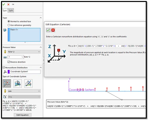
Figure 8 - Nonuniform pressure creation in SOLIDWORKS Simulation
The formula we used for this sample is shown below. You may copy and paste it into your own project to test it, then make any tweaks needed for your application.
Sample equation to copy:
int((10-"x")/200+1) * (-7/800*"x"^2+3/16*"x") + int(("x"-10)/200+1)*int((90-"x")/200+1) * (1/80*"x"+7/8) + int(("x"-90)/200+1) * (-17/800*"x"^2+307/80*"x"-685/4)
Pressure units: N/m^2
Units for x, y, and z: mm
Conclusion
After some mixed up units and a bit of trial-and-error, Todd was able to get his Simulation flying along nicely.
Todd could have also tried using the split line method which involves splitting the faces of his airfoil in the chord direction, but while this method avoids the use of the extra equations, this method also has a few drawbacks:
- If the load changes, the split lines may need to be moved and therefore the model needs to be re-meshed.
- Changing model topology may require mesh controls, bonded contacts, mates, and other items associated with those original faces to be re-attached or cleaned up.
- Split lines may create additional undesirable “mesh edges” in the model.
If you have any questions about the approach discussed in this article or would like to schedule a session with one of our engineers to work with you on one of your own simulations, please contact our technical support or sign up for an Application Mentoring Session with a member of our team!
Footnote:
1 sgn() is also close to what we need, but it creates an additional condition with sgn(0) = 0 that is undesirable.
Learn More About SOLIDWORKS Simulation
SOLIDWORKS Simulation Water Pressure Load
Frequency Study Plot with SOLIDWORKS Simulation
Managing SOLIDWORKS Simulation Results with PDM
7 Steps to Perform a Fatigue Analysis in SOLIDWORKS Simulation

About Shaun Bentley
Shaun Bentley is passionate about applied mathematics and engineering, which led him to pursue and understand real world applications of FEA, CFD, kinematics, dynamics, and 3D & 2D modeling. He teaches many simulation classes to both new and advanced users attending training at GoEngineer. Since 2006, Shaun has been working with simulation tools to solve real world engineering problems. With every new project, he seeks to find ways to push simulation to its uppermost limits, even going so far as to write bespoke code and macros. He has passed the Michigan FE exam and mentors or consults for virtually any industry that uses SOLIDWORKS, especially automotive and automated tools. He is a speed 3D modeling champion and one of the first Certified SOLIDWORKS Experts in Simulation in the world.
Get our wide array of technical resources delivered right to your inbox.
Unsubscribe at any time.