How to Use SOLIDWORKS 3D Texture Tool
SOLIDWORKS 2019 introduced a new tool called 3D Texture. In this article, we will explore what this tool allows us to do, when it may be applicable, and of course where to find it.
What Does the SOLIDWORKS 3D Textures Tool do?
The 3D Textures tool will transform a Textural Appearance into 3-dimensional geometry that can be manufactured using a 3D printer or other manufacturing methods. The grip bumps on a bicycle handle or pistol grip are examples of this.

How does the 3D Textures Tool Work?
The 3D Textures tool uses the color differences in a Textural Appearance to raise the level of the predefined color. We will explore this in much more detail later on.
What are Textural Appearances, and where can they be found?
A Textural Appearance is a grayscale image consisting of patterns using black and white colors.
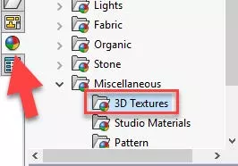
To find one of these appearances, click the Appearances, Scenes, and Decals Task Pane icon, browse to the Miscellaneous folder > 3D Textures folder.
How to apply Textural Appearances in SOLIDWORKS
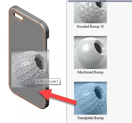
To add the appearance, browse to the 3D Textures folder and drag one of the textures to a model face.
In this example, I am dragging the Treadplate Bump texture onto a face of a cell phone cover.
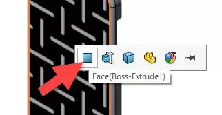
Be sure to select Face on the pop-up Context Toolbar to avoid adding the texture to the entire body.
How to edit the appearance
If the appearance is not scaled to your preference, you can change this by editing the texture.
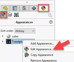
To do so. click DisplayManager, make sure View Appearances is highlighted, then right-click on the texture and choose Edit Appearance...
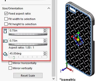
In the PropertyManager, click Advanced and then the Mapping tab. Under Size/Orientation, you can change the width, height, and angle of the appearance. For this example, I have set the width and height at .75in, and the angle to 45 degrees.
Where is the SOLIDWORKS 3D Texture Tool Located?
Once a Textural Appearance is added and scaled to preference, expand the Solid Bodies folder in the FeatureManager Design Tree, right-click and choose the 3D Texture icon.
![]()
Note: This will convert the model to a graphics body, so it should be last in the design process.
How to use the 3D Texture PropertyManager
Once the 3D Texture command has been enabled, the PropertyManager is displayed. This is where we will tweak some of the settings to transform the texture into 3-dimensional geometry.
- In the 3D Texture PropertyManager, expand Texture Settings and click the check box next to the texture you wish to convert to 3D.
- Enable the check box Convert this texture to 3D
- The check box White up Black down decides which color will be raised. For this example, the Treadplate Texture is white and the background is black. I have enabled the check box.
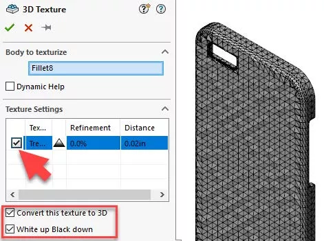
As you can see in the image above, the texture is poorly defined. The next set of options in the PropertyManager will allow us to refine the texture and give depth.
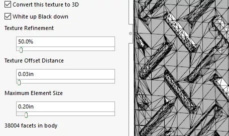
- Texture Refinement adds facets to better match the contours within the grayscale image.
- Texture Offset Distance specifies the maximum offset of the texture from the body.
- Maximum Element Size specifies the maximum size of the largest mesh facet in the mesh. Lower values create smaller mesh units and smoother models.
For the treadplate texture, I started off with a refinement of 50%, an offset distance of .03 inches, and a max element size of .2 inches. The image below reveals the results at these values.
When the values are increased for Texture Refinement and decreased for Maximum Element Size, the result will be a better looking mesh.
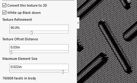
It is important to note that higher refinements will also place a higher demand on your CPU. For this reason, it may be better to refine in small increments until you get the desired results.
What about the Graphics Body?
Since this process does convert the model to a graphics body there are a few things to consider. In the FeatureManager Design Tree under the Graphics Bodies folder you will see one of two types:
 Indicates an open body and is not considered watertight.
 Indicates a closed body and is considered watertight.
To prepare the file for manufacturing you can convert the graphics body into a mesh BREP body.
- To do this, go to Insert > Features > Convert to Mesh Body

- Only closed graphics bodies can be converted to a mesh BREP body
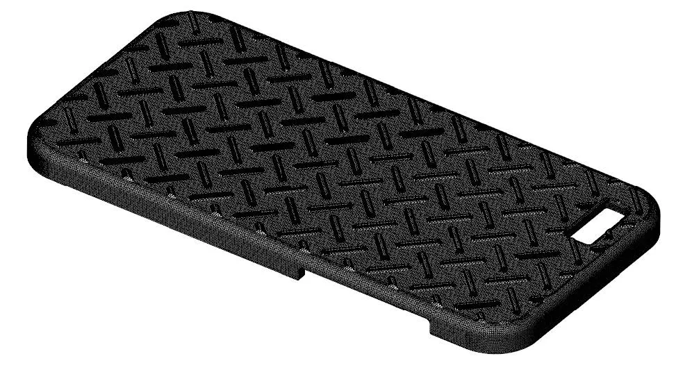
Here is an example of the final model.
More SOLIDWORKS Tutorials
SOLIDWORKS Weldment Profiles & Weldment Tools Guide
SOLIDWORKS Mold Tools: Split Line & Parting Line Explained
How to Use Layers in SOLIDWORKS Drawings
SOLIDWORKS Mold Tools - Shut Off Surfaces, Parting Surfaces, and Tooling Split

About Zach Brown
Zach Brown is a certified SOLIDWORKS Expert and a Technical Support Engineer. Prior to working at GoEngineer, he spent 15 years as a mechanical designer, CAD support tech, and instructor using SOLIDWORKS. His hobbies include playing guitar, riding motorcycles, and skiing.
Get our wide array of technical resources delivered right to your inbox.
Unsubscribe at any time.