SOLIDWORKS Mold Tools - Shut Off Surfaces, Parting Surfaces, and Tooling Split | GoEngineer
Welcome to another SOLIDWORKS Mold Tools tutorial. In the previous article, we discussed Draft Analysis and Scale. In this article, we'll take a look at shut off surfaces, parting surfaces, and tooling split mold tools.
Using Shut Off Surfaces, Parting Surfaces, and Tooling Split
After we have verified that our molded part has an adequate draft and contains an appropriate parting line, it’s time to create our mold pieces. To do this, we first must shut off any through-holes using Shut Off Surfaces. We then create a parting surface that separates our mold pieces, and finally a tooling split to generate the parts of the mold.
Shut Off Surfaces
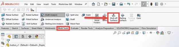
Shut Off Surfaces is located under Mold Tools > Shut Off Surfaces in the CommandManager. If the Mold Tools tab is not visible, simply right-click on any of the existing tabs and select Mold Tools from the flyout menu to enable it.
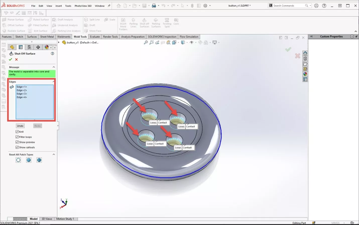
With Shut Off Surfaces selected, we simply select the edges of any through-holes to create surface bodies to cover them. This is a necessary step for creating the mold and indicates where the mold halves will meet inside the holes.
Parting Surfaces
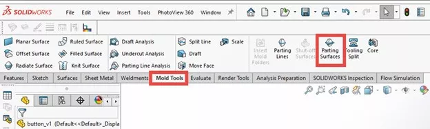
With the through-holes shut off, we are ready to specify our parting surface. The Parting Surfaces tool is located in the CommandManager near Shut Off Surfaces.
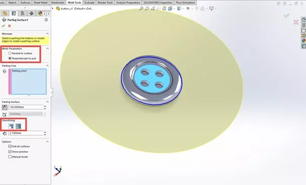
With Parting Surfaces tool selected, we need to specify the direction of our cut and the size of our surface. It’s typical for the tool to automatically cut in the wrong direction, but we can reverse this by toggling the arrow in the PropertyManager. We then want to specify the size of the parting surface, which generally needs to be quite large—large enough to contain the entire mold body that we will be creating.
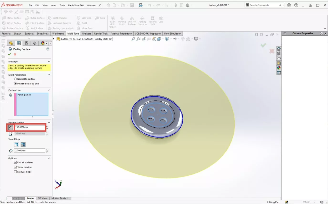
Additional settings exist including Mold Parameter (normal to surface, perpendicular to pull) and Smoothing. Mold Parameter specifies the orientation of the parting surface, and Smoothing will automatically smooth sharp corners.
Tooling Split
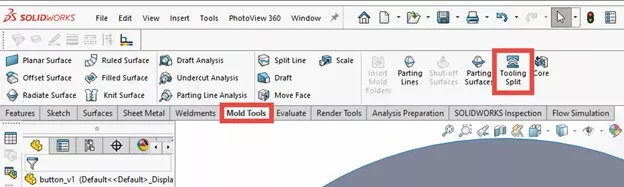
With our parting surface completed, we are ready for our tooling split. The Tooling Split tool is in the CommandManager near Parting Surfaces.
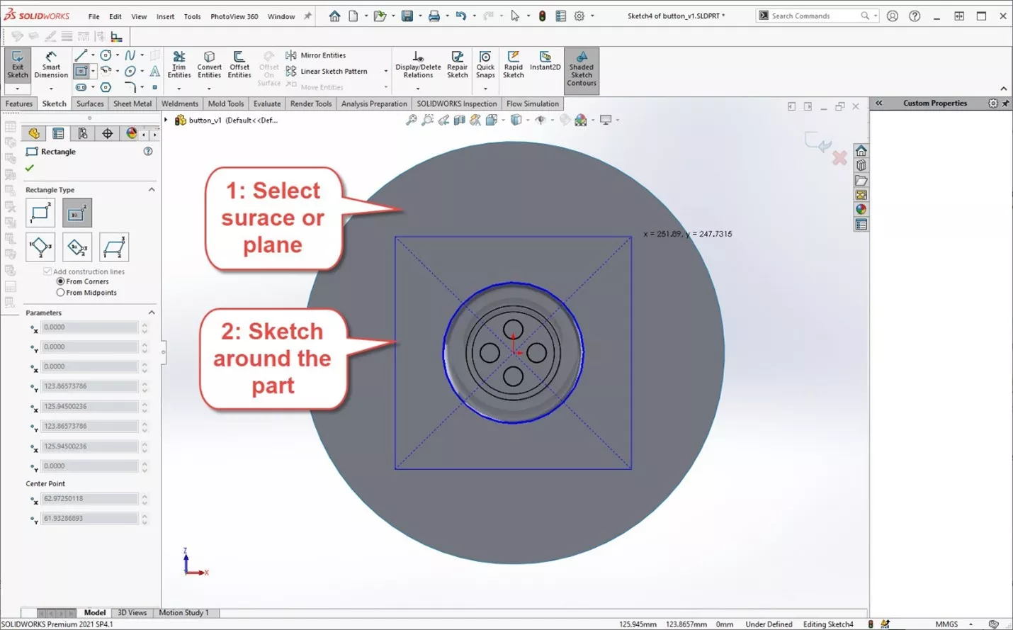
With the Tooling Split tool selected, we first select a face or plane on which to sketch. Then we sketch around the molded part, keeping our sketch contained on the parting surface. For this part, I sketched on the parting surface itself.
When we exit the sketch, it automatically begins an extrusion to form our mold.
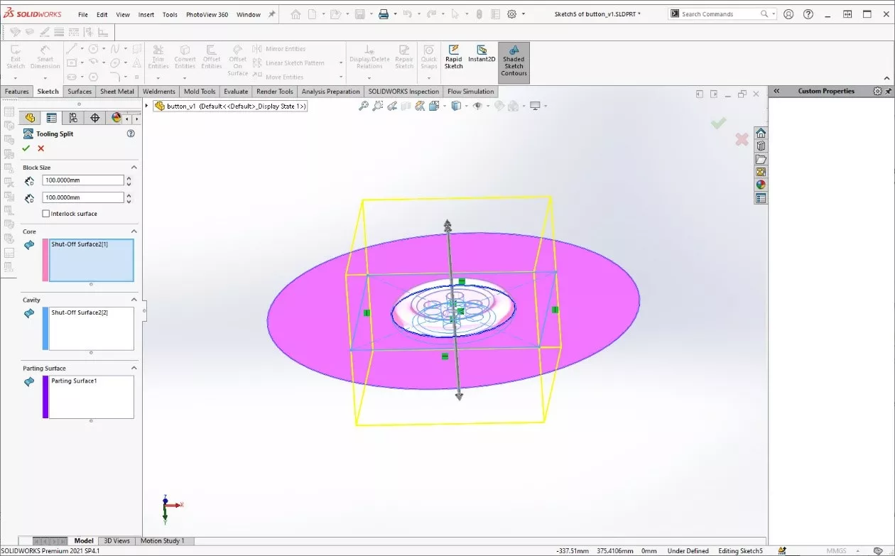
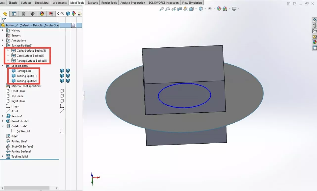
When we hit the green check, the extrude completes. We now have three surface bodies and three solid bodies. The surfaces were used by SOLIDWORKS to create the mold, and the solid bodies are as follows: the molded part, the top half of the mold, and the bottom half.
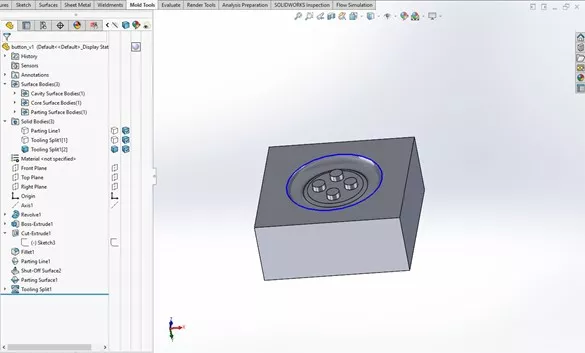
By hiding the surface bodies and toggling the transparency, we can view the button inside the mold and the mold halves themselves.
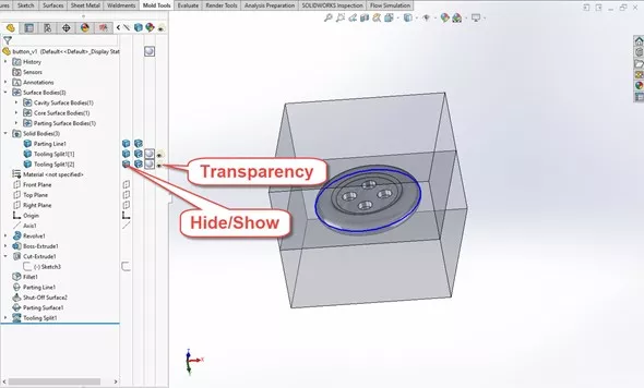
This lets us inspect the mold pieces individually.
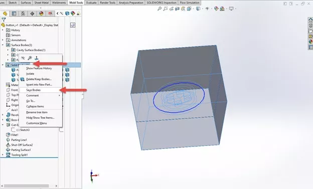
Save Bodies
After completing the tooling split and verifying that the mold pieces are correct, we can save each body out as its own part file. To do this, simply right-click on the Solid Bodies folder and select Save Bodies.
Interested in learning more tips and tricks to get the most out of your SOLIDWORKS? Check out our YouTube channel. We have an extensive library of videos from tips and tricks to what’s new videos, in-depth webinars, and much, much more! Check https://goeng.io/youtube for more and do not forget to subscribe and hit the bell icon to get notifications for all our great new video content.
More SOLIDWORKS Tutorials
SOLIDWORKS Mold Tools - Draft Analysis & Scale
SOLIDWORKS Display Scaling Solutions
Inserting Logos Into SOLIDWORKS Parts and Drawings
How to Create a Lip/Groove Feature in SOLIDWORKS
SOLIDWORKS eDrawings Professional vs Viewer
SOLIDWORKS MOLD DESIGN TRAINING
Learn manual mold creation techniques and mold tools by enrolling in training with GoEngineer. Learn more below.


About Gary Ballentine
Gary Ballentine is a Mechanical Engineer based out of our Headquarters in Salt Lake City, Utah. He earned a Bachelor’s degree from the University of California, Davis, a certification in Technical Writing from San Francisco State University, and a Bachelor’s degree in Mechanical Engineering from the University of Utah. Gary has been part of the GoEngineer family since April 2019 as a Support Engineer and Certified SOLIDWORKS Instructor.
Get our wide array of technical resources delivered right to your inbox.
Unsubscribe at any time.