SOLIDWORKS: Creating a Derived Centerline in a Twisted Sweep
In SOLIDWORKS, generating a sweep with a twist value can make some modeling tasks much simpler. However, there are limits to what a sweep feature can do.
Creating a Sweep in SOLIDWORKS
A single circular profile along a path is provided for in the Sweep PropertyManager, so we don’t need to create a profile sketch for that. Simply enter the desired diameter and set any other options.
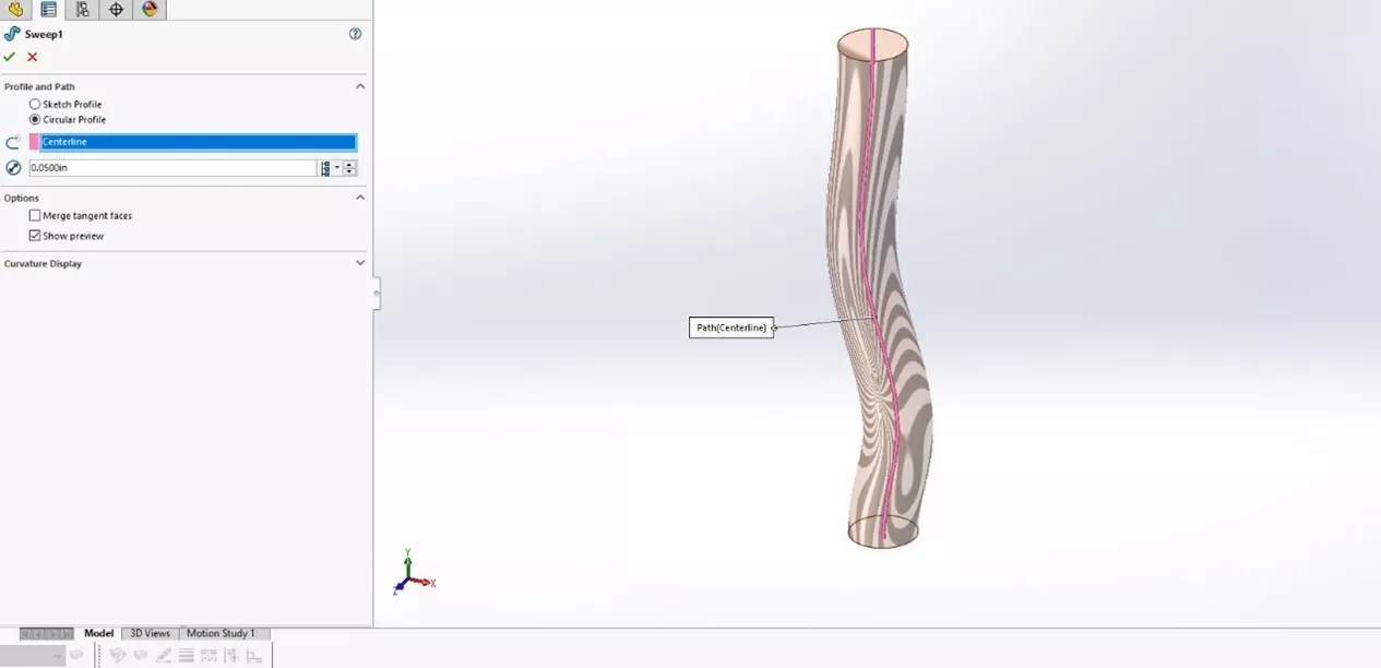
Sometimes we need a sweep that is off-center of the centerline. This is also easily accomplished by making sure the profile sketch is connected to the path.
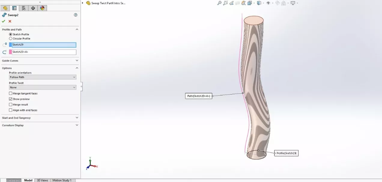
By using the twist options, you can easily twist the profile around the path.
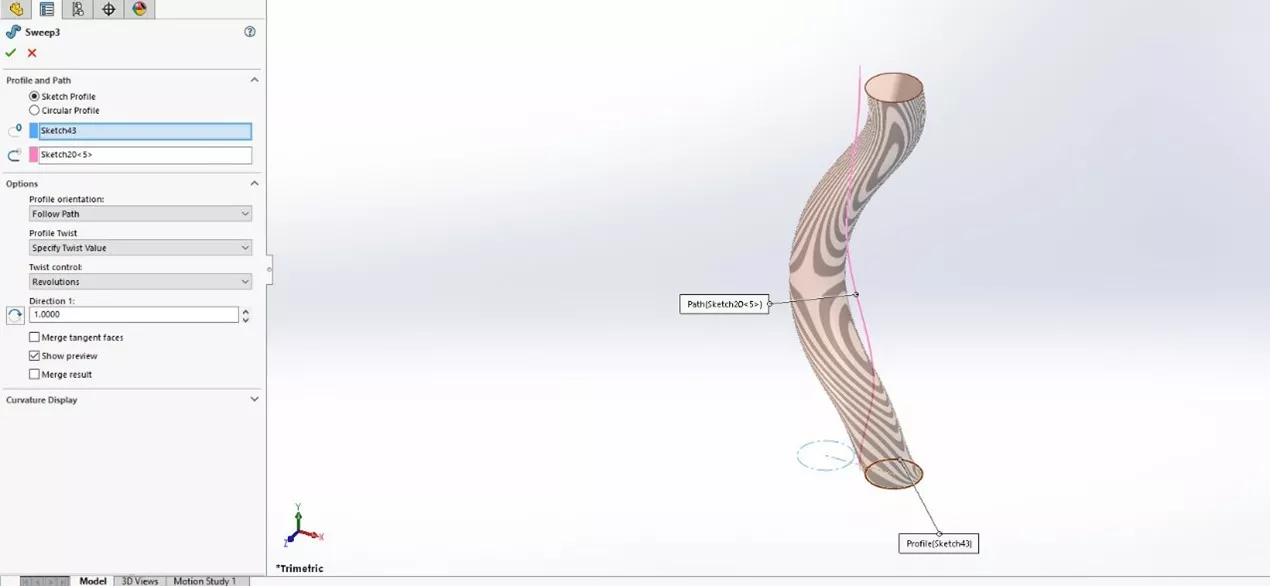
Additionally, we can add another entity in our profile sketch to form a twisted pair of bodies along the path.
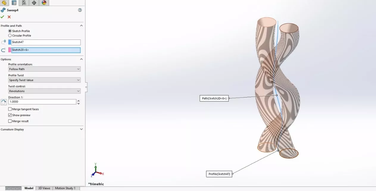
If we want to continue the sweep in another direction but keep a tangent relation to the swept profile path, there is no centerline path to connect to. To extend the sweep, we will need to derive a centerline for it. We’ll walk through an example later of modeling a twisted pair of wires, extended along different paths, with terminal ends. Much like a purchased wiring assembly. Now on to creating the derived centerlines.
Creating a Derived Centerline
Since there is no automatically generated centerline, we need to create one. Here I’ll turn to the surfacing tools. To create the centerline, we can use a similar sweep using a surface this time. Here, I created the sketch for my profile on the same plane as the solid sweep. I created a single line from center to center of the entities used for the solid sweep.
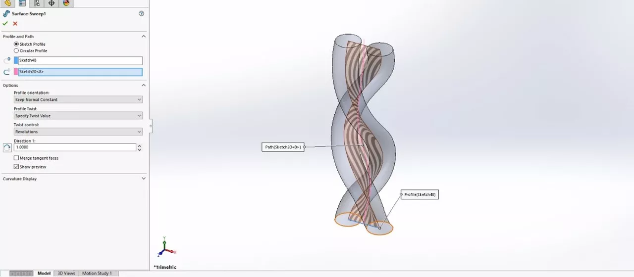
I used the same parameters in my surface sweep that I used in my solid sweep. The result is a surface sweep along the same path as the primary profile using the same twist options and a separate surface body is created.
Now I can use the edges of the surface sweep to create a 3D sketch that is the centerline of the swept bodies. Creating a new 3D sketch, I'll use the convert entities function on the edge of the surface sweep body to create a derived centerline (shown in magenta).
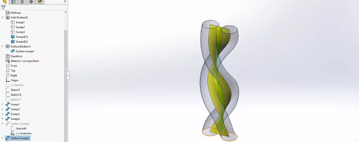
With the centerlines created, I can then create additional bodies or segments, aligning with the solid sweep.
Extending the Sweep
Here I have used the above methods to create a model resembling a twisted pair of wires. The centerline for the twisted sweep is green and the derived centerlines are magenta.
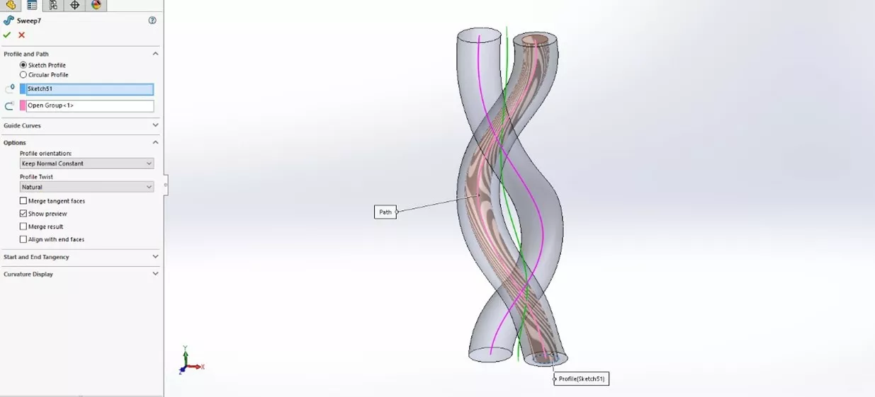
To get the extension of the wires out of the ends that will receive terminals, I need to extend the derived centerline paths. For this, I will again use a 3D sketch with relations back to the derived centerline. The derived centerlines are again in magenta and the primary sweep centerline is in green.
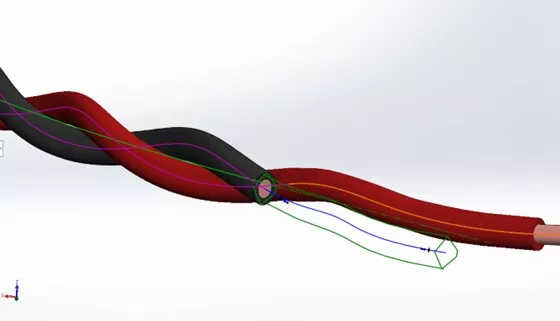
Here I have extended the derived centerlines to create paths for the insulators and actual wire core.
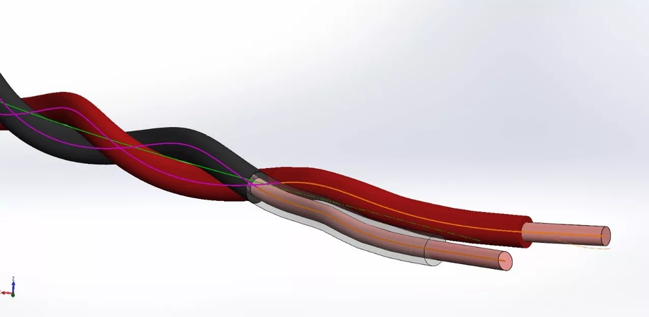
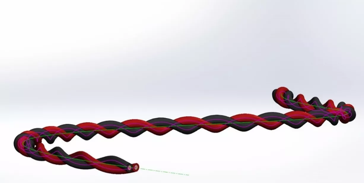
When complete I can use this part in an assembly for adding and positioning the terminals.
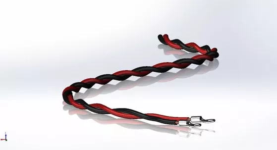
The paths used in the extension can be adjusted later if required. Applying the same techniques on the other end, a connector or other termination can be added. There are ways of using multiple surfaces in the creation of a solid model that would be difficult to accomplish otherwise. The technique of using surfaces in your SOLIDWORKS modeling can sometimes help in situations like this.
I hope you found this SOLIDWORKS tutorial helpful. Check out more tips and tricks listed below.
Expand Your SOLIDWORKS Skillset
Join the SOLIDWORKS Forums on the GoEngineer Community
SOLIDWORKS Sweep in Two Directions
Using the Curve Through XYZ Points Tool in SOLIDWORKS
SOLIDWORKS Electrical vs Routing: Which Product Should I Choose?
![]()
About Martin Adams
Martin Adams is a Senior Technical Support Engineer at GoEngineer supporting SOLIDWORKS CAD and SOLIDWORKS Electrical products. In addition to a CSWE certification, he has a Bachelor's degree in Industrial Engineering and an Electrical Associate's degree. Prior to joining GoEngineer in 2019, he worked for almost twenty years on prototype automotive instrumentation. He also served as an Electrician's Mate in the US Navy. His favorite activities are fishing and spending time around a campfire with friends.
Get our wide array of technical resources delivered right to your inbox.
Unsubscribe at any time.