SOLIDWORKS Performance and How-To for Cosmetic Threads & Physical Threads
Complex features, like physically modeled threads, increase the rebuild times of SOLIDWORKS part files.
Table 1 shows the rebuild times on a simple part with a thread created using multiple methods.
This document will prove these rebuild times and explain the various methods used to create these threads.
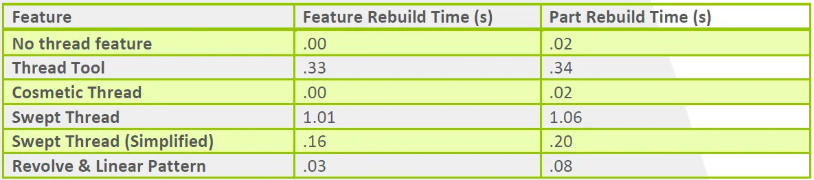
Table 1. Rebuild times of cosmetic and physical thread methods.
Establishing the Baseline
This simple part file of a turned cylinder was used as the baseline for all methods. Figure 1 shows the dimensions of this part file.
All methods use Tools, Evaluate, Performance Evaluation to measure rebuild times.
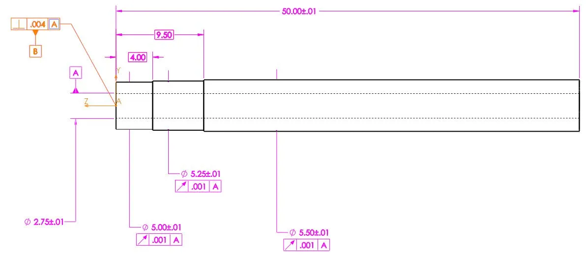
Figure 1. Dimensions of baseline geometry.
Thread Tool
SOLIDWORKS 2016 was released with the Thread tool. This tool creates helical, non-tapered, physical threads based on a thread profile library. To see the thread tool in action, please watch this video.
Custom Threads
The profile library comes with a downloaded set of profiles, generally located at C:\ProgramData\SolidWorks\SOLIDWORKS 2017\Thread Profiles. If custom thread profiles are needed, we recommend moving this folder to a non-SOLIDWORKS location. Thus, if SOLIDWORKS is ever uninstalled, the user will not lose their customizations. Point SOLIDWORKS to the new location via Tools, Options, System Options, File Locations, Thread Profiles.
A custom thread profile has a few requirements.
- Create one vertical centerline connected to the origin.
- Dimension this centerline to define the pitch of the thread.
- Must be a library feature part file. (File, Save As, Library Feature Part).
- The thread sketch must be added to the library. (Right-click on sketch, ‘Add to Library’).
Some additional recommendations may make the process cleaner.
- Do not have more than one sketch or closed contour in the thread profile.
- The vertical centerline and origin will by default sit at the diameter of the cylinder selected.
- If the thread is drawn to the right of the vertical centerline, by default the thread will extrude out of the geometry.
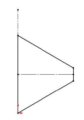
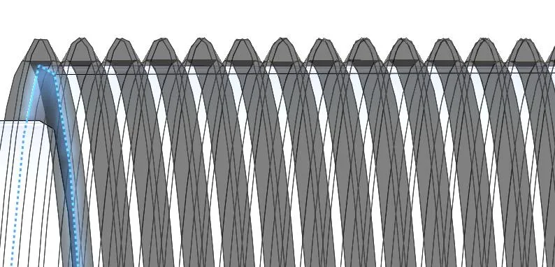
Figure 2. Tap thread profile, and the type of geometry it may create.
Thread Feature
The thread tool is very versatile. It can easily create cut or extruded threads, alter start and end faces, or change pitch and diameter on the fly. The abilities of the tool are covered well in the Help menu. One major limitation is an inability to create thread features on tapered/conical faces.
The more references a feature has, the longer it takes to rebuild.
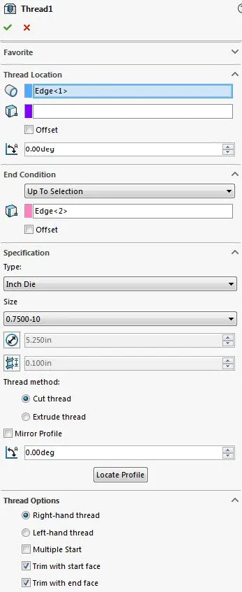
Figure 3. Thread tool property pane.
Using Performance Evaluation, we see that the thread feature takes 95.91% of the total part rebuild time, or approximately 0.38s out of 0.39s.
Cosmetic Threads
A cosmetic thread is a graphical representation of a thread that can be called out on a drawing. It is purely an annotation created one of two ways.
- Within Hole Wizard, using Straight or Tapered Tap, hit the checkbox for ‘thread callout’ or ‘cosmetic thread’.
- Within a Part, Assembly, or Drawing file, selecting Insert, Annotations, Cosmetic thread, and defining the thread via faces, edges, and planes.
In this example, only method (2) can produce the annotation required. For a standard thread select the diameter and thread depth. For a conical/tapered threat, select the minimum diameter edge and the start face/plane.
Toggle the display of the dotted lines and zebra stripes via Tools, Options, Document Properties, Detailing, ‘Cosmetic threads’ and ‘Shaded cosmetic threads’.
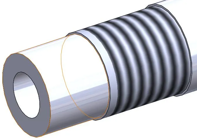
Figure 4. Cosmetic Thread.
The cosmetic thread annotation doesn’t appear in the performance evaluation. The entire part file took 0.02sec to rebuild, and that time to rebuild was due to the sketch defining the cut-revolve feature.
Swept Thread
Manually create a thread using a Helix curve, a sketched profile, and the Sweep feature. The swept thread method is required for physically modeled tapered threads. Watch this video to see the necessary steps.
Create a helix curve via Insert, Curve, Helix/Spiral. A sketch circle is required to define the starting diameter and start point of the helix. Watch this video to learn how to vary pitch, diameter, or height throughout the helix.
Draw the sketch profile perpendicular to the start point of the helix. To properly connect the sketch to the 3D curve, use a Pierce relation. Watch this video to learn how to use the Pierce relation.
Finish the process using Swept Cut or Swept Boss to produce a cut thread or extruded thread. On my system, this took 1.06s to rebuild, with the swept-cut feature taking 1.01s.
Swept Thread (Simplified)
We can simplify the swept feature using “Specify Twist Value”. A helical curve is never generated, thus reducing the rebuild time, but also reducing the customizability of the helical cut. For example, we can not create a tapered helix cut with this method.
Create two sketches, one with the profile positioned, and another with a straight line spanning the depth of the thread, and representing the axis of the helix. These sketches should be parallel.

Figure 5. Simplified Sweep, sketch orientation.
In the sweep command, set Profile Orientation: Follow Path, Profile Twist: Specify Twist Value, and Twist control to either degrees or revolutions. See Figure 6 for example.
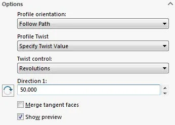
Figure 6. Simplified helical sweep, Cut-Sweep Options.
The Cut-Sweep feature takes 0.16s to rebuild, and the overall part takes 0.20s to rebuild.
Revolve & Linear Pattern
This method produces the general look of a thread, but patterns a revolve feature rather than creating a helical shape. This article provides a summary of performance comparisons for pattern features.
First, create a revolved boss or revolved cut using the thread profile. Then use Linear Pattern to pattern that cut along the axis of the turned part. This video shows the essentials of the revolve feature, and this video shows the essentials of the linear pattern feature around 12:00.
Hit the checkbox for “Geometry Pattern” in the Linear Pattern Options. If applicable, it always reduces rebuild times. (See Table 2.) See more proof in this video.

Table 2. Geometry Pattern on and off comparison.
Conclusion
In every scenario, the physical thread features topped the list for rebuild times. If a physical thread is required, and one of these methods is used, we recommend creating a “Simplified” configuration of the part file where this feature is suppressed. Thus, most assembly files and drawing views using this component can reference the “Simplified” configuration, thus reducing rebuild times in those documents as well.
Download the SOLIDWORKS 2017 files used in this example.
Learn More about SOLIDWORKS Cosmetic Threads
To Thread or Not to Thread? Hyper Threading and SOLIDWORKS Performance
SOLIDWORKS Cosmetic Thread View Options
SOLIDWORKS Cosmetic Thread Upgrades

About Shivani Patel
Shivani has a background in aerospace engineering, and is the Engineering Manager for southern Texas. She has the Elite certification in SOLIDWORKS and is happy to jump into anything in the SOLIDWORKS licenses. Her main specialty is Simulation - and has spent the past 6 years digging into the Motion Analysis, FEA and CFD programs and supporting many of our oil and gas customers in the south.
Get our wide array of technical resources delivered right to your inbox.
Unsubscribe at any time.