SOLIDWORKS Sheet Metal Lofted Bend Manufacturing Methods Bent & Formed
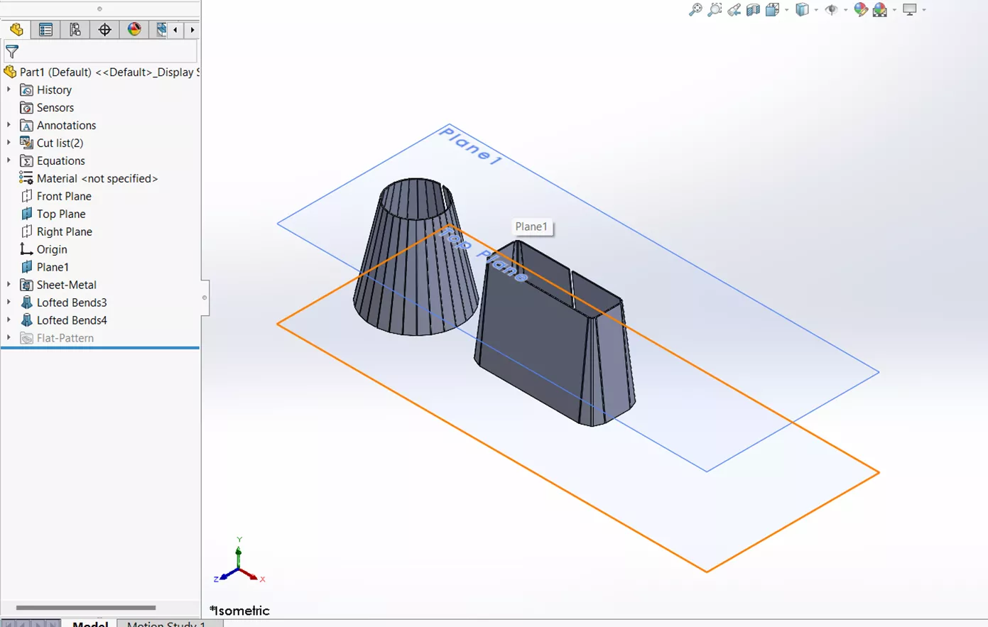
The SOLIDWORKS Sheet Metal Lofted-Bend command is an efficient way to create odd-shaped sheet metal parts.
![]()
A Sheet Metal Lofted-Bend is similar to the SOLIDWORKS Loft and Boundary features, in that they require two or more profiles. The main difference is that the Sheet Metal Lofted-Bend doesn’t require a guide curve, and the contours need to be open.
There are two different types of Lofted Bends: Bent and Formed.
Manufacturing Method Bent Tutorial
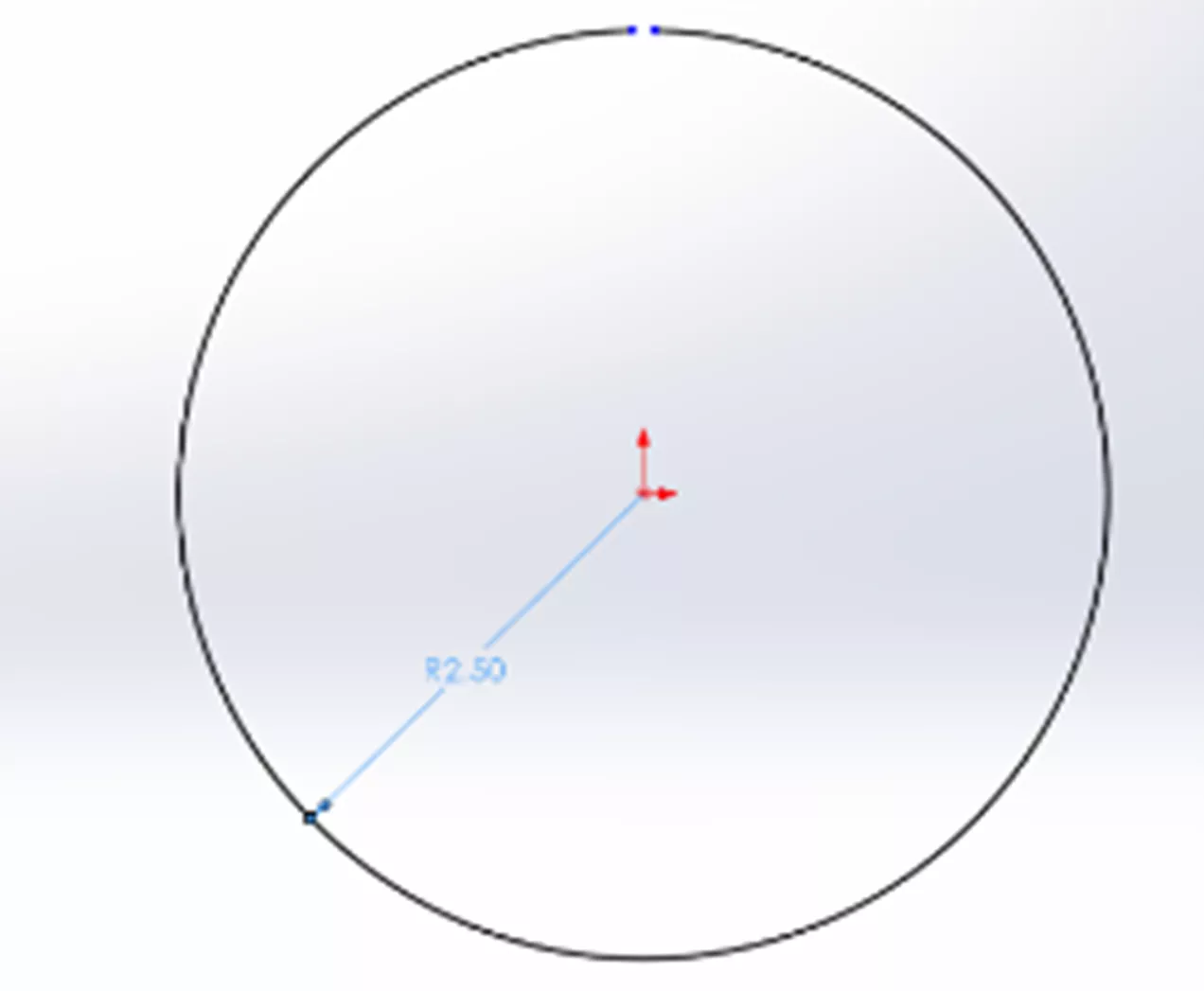
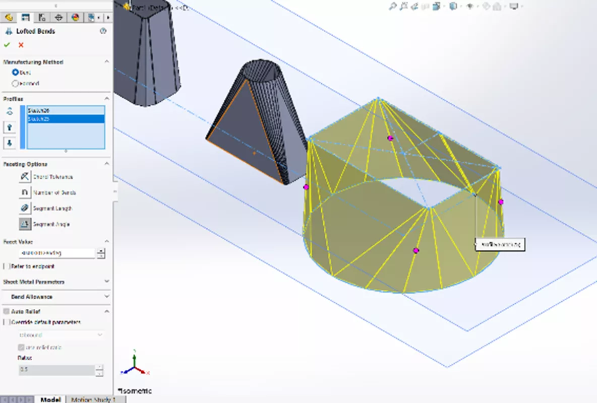
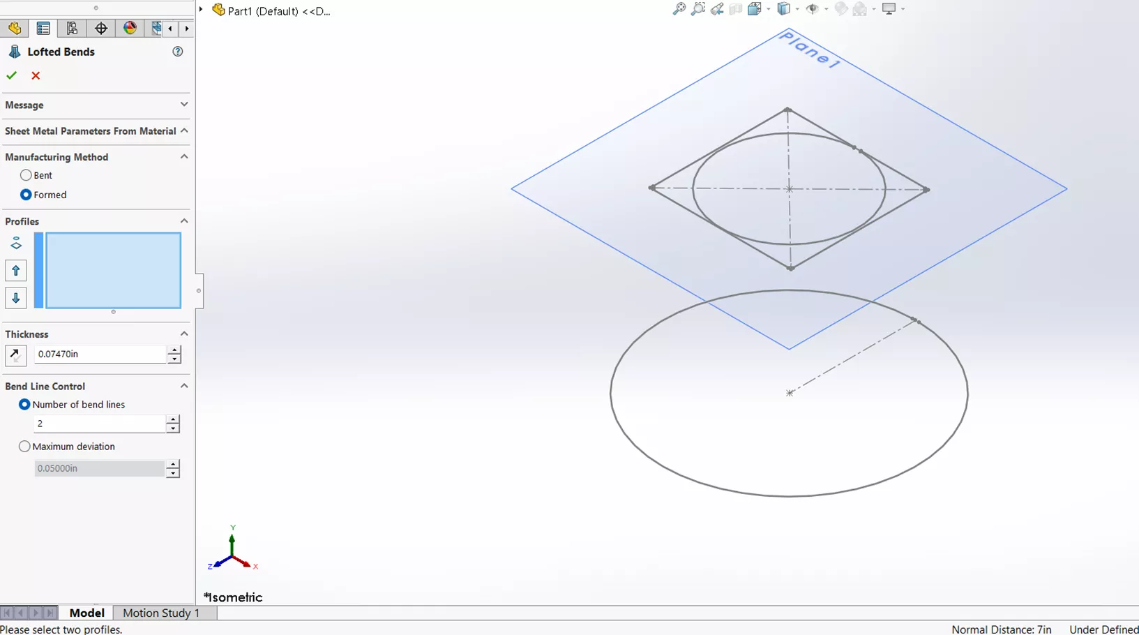
Bent Lofted Bends creates traditional sheet metal bends specified by the user, and you can use a gauge table. To do this, create an open contour circle on the top plane with a dimension of DIA 10”, then a reference plane 7” from the top, with another open contour circle with the dimension of DIA 4”.
For this profile, I will select both of my sketches.
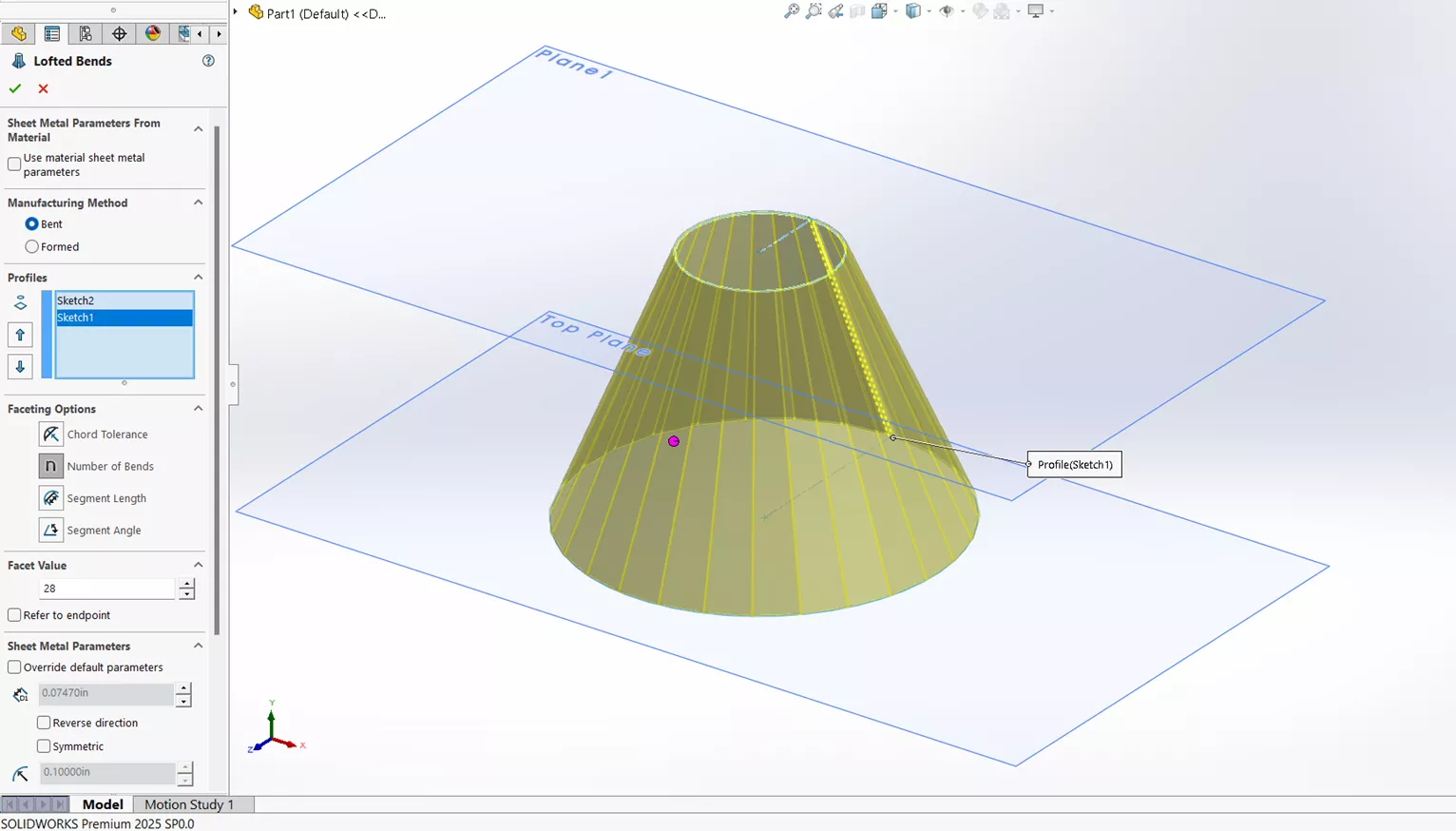
Next are the faceting options. (For this specific example, I will select Number of Bends.)
- Chord Tolerance sets the maximum distance between the arc and the linear segment.
- Number of Bends sets how many bends are applied to each transition.
- Segment Length specifies the maximum length of the linear segment.
- Segment Angle specifies the maximum angle between two adjacent segments.
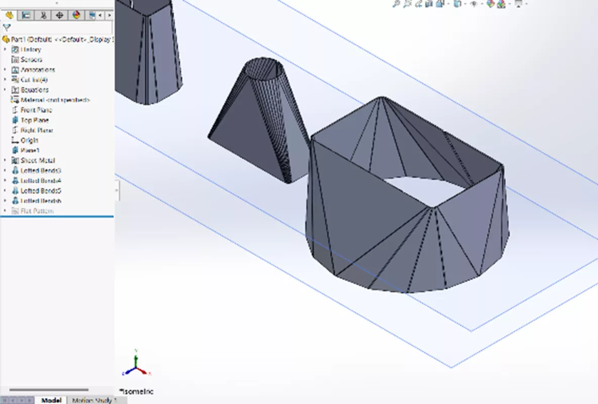
I will set the Facet Value to 28 and uncheck Refer to endpoint. Clicking the green check results in the following:
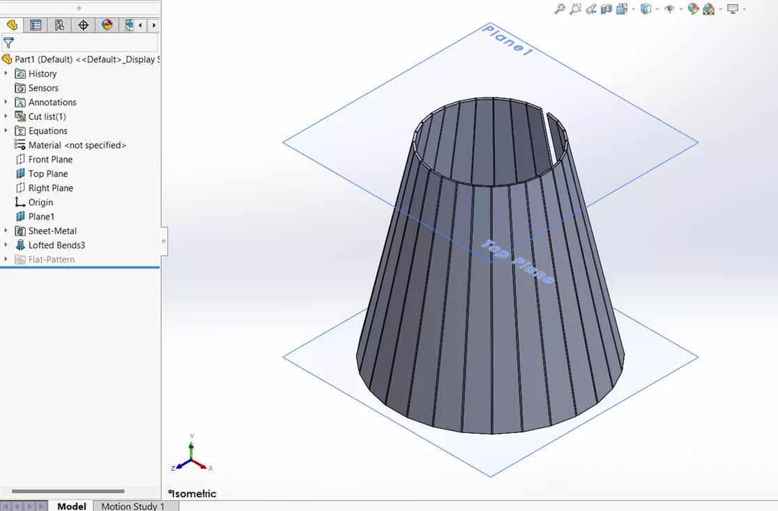
Here, I will try the Chord Tolerance option with a Facet Value of .125.
Clicking the green check results in the following:
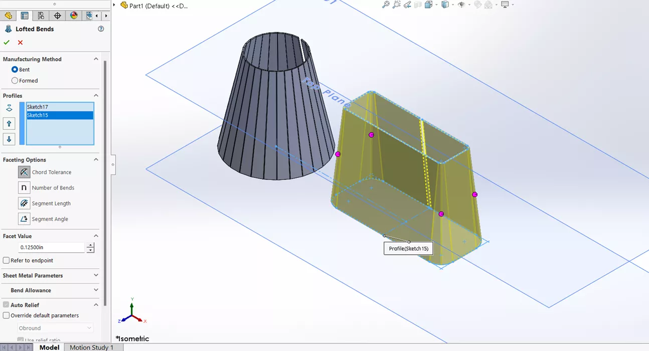
In this example, I will try the Segment Length with a Facet Value of .25. Clicking the green check results in the following:
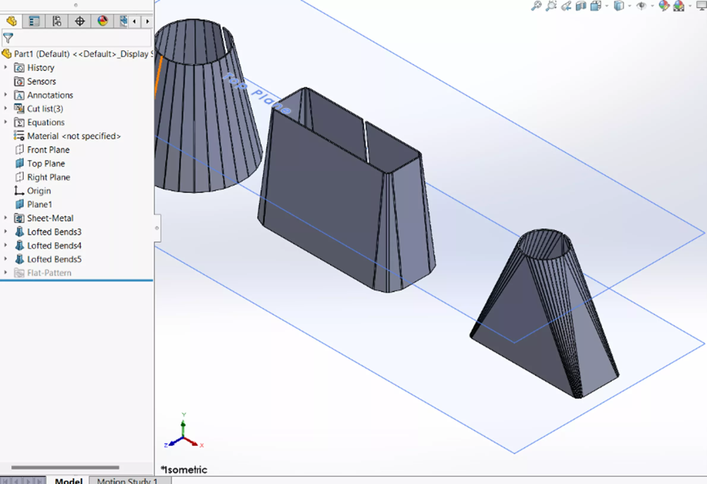
In this last example, I will use the Segment Angle option. I intentionally want this to be as wacky looking as possible to show the full extent of the Lofted-Bent Manufacturing Method. I will set the Facet Value option to 30 degrees, select the green check mark, and my drawing will result in the following:
Manufacturing Method Formed Tutorial
Formed Lofted-Bend – You can see that I lost a lot of the sheet metal options when the Formed method was selected. This Formed option does not use traditional sheet metal forming tools, such as a manufacturing method like a press break machine. Therefore, I don’t need parameters such as K-Factor and Relief options.
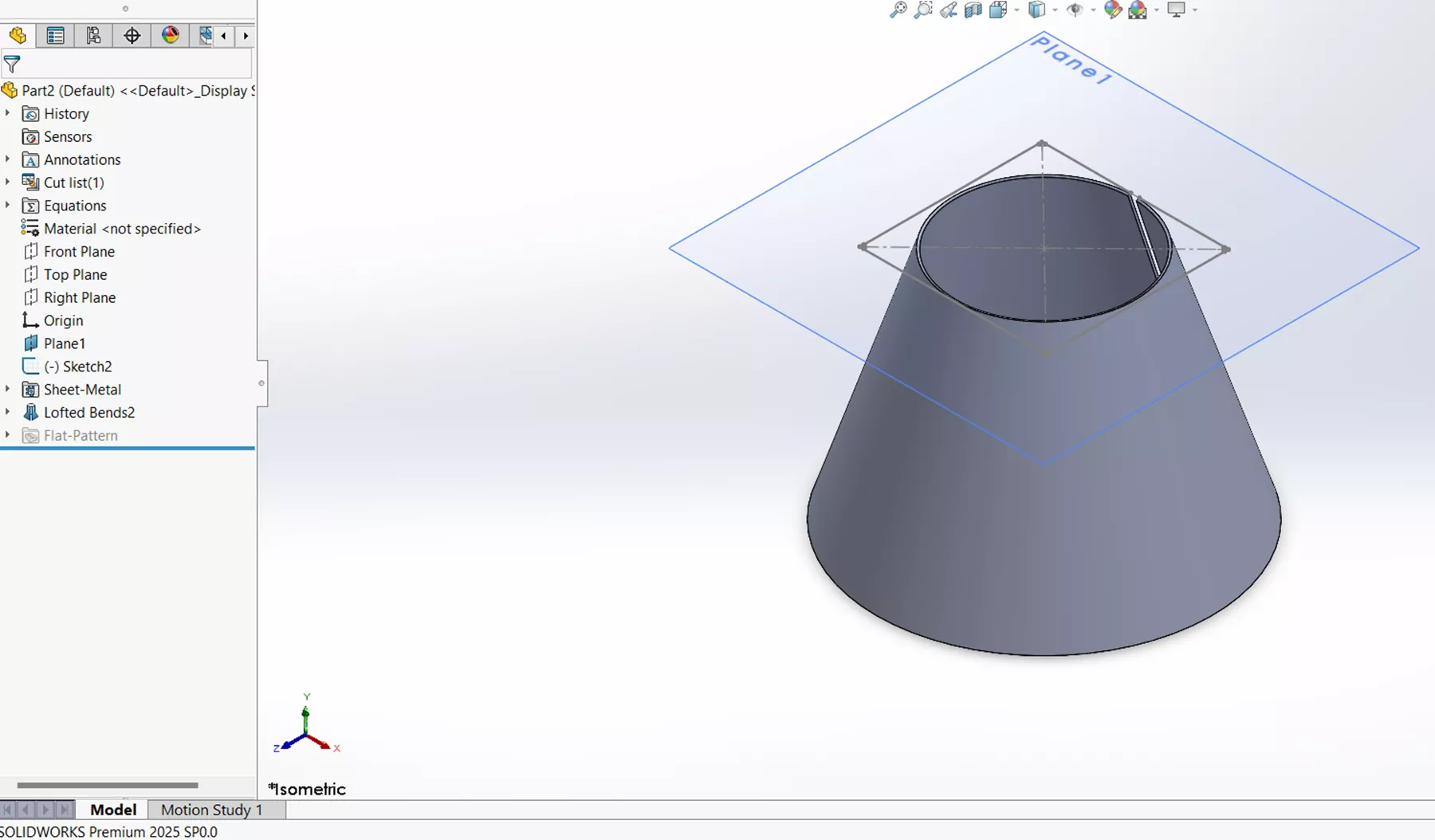
I will pick both circle sketches as my profiles and change the number of bend lines to 5. Notice when I select them and click the check mark, that I have a pristine shape. This is because we are assuming a forming method that gives us this kind of amazing circular geometry.
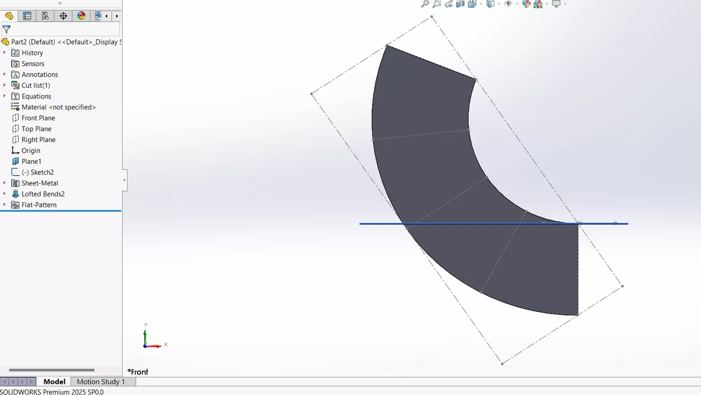
Once I go into the flat pattern, you can see the sheet metal equivalent of this formed part with the 5 specified bends.
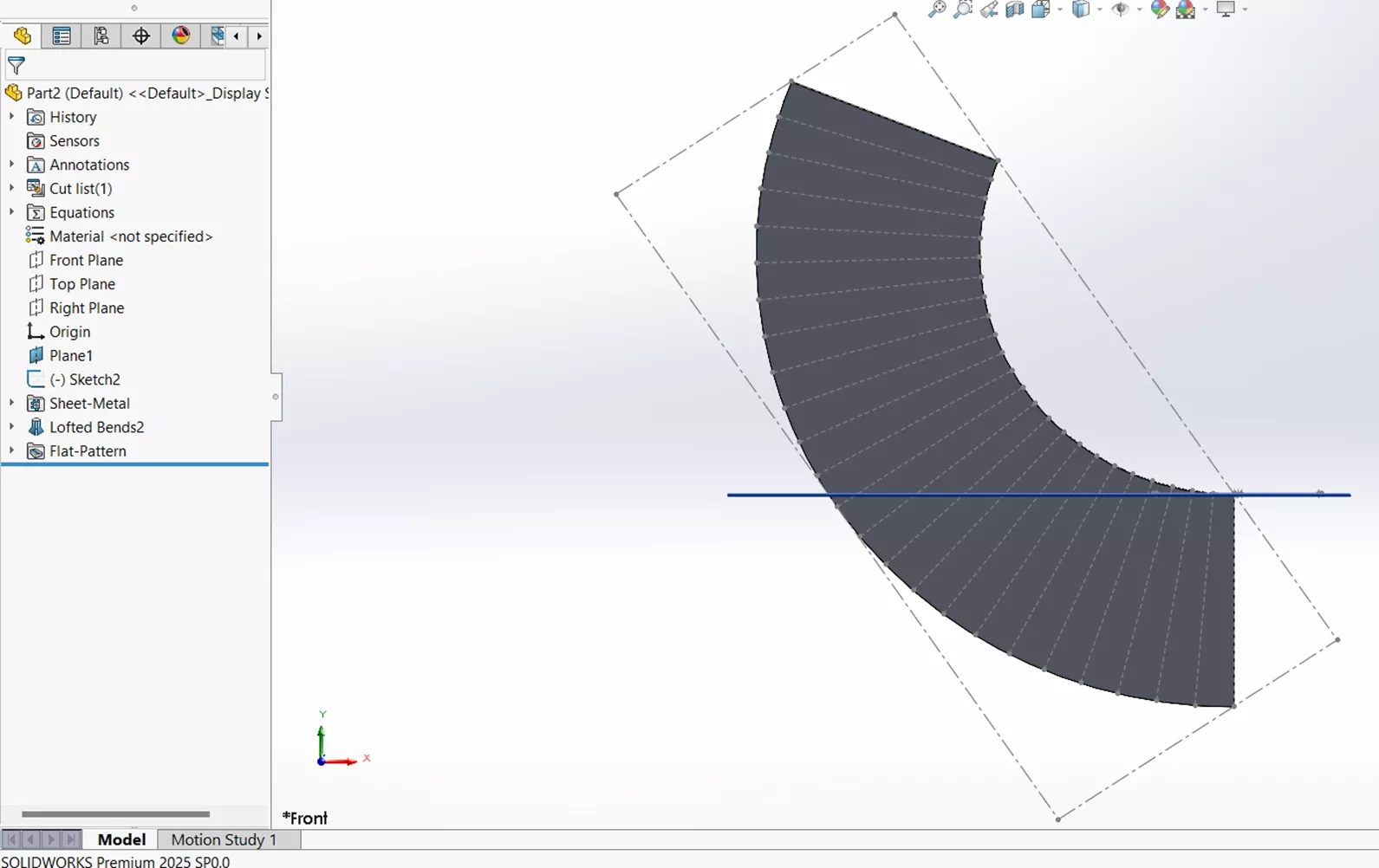
Now let's go back into the Lofted-Bend feature and switch from Number of bend lines to Maximum Deviation. I will leave the default number, click the check mark, and go back into the flat pattern. Looking at the flat pattern and the default number of .050, which is extremely tight, I will need a few more than five bend lines to achieve this part.
I hope you found this article interesting and illuminating as to how Sheet Metal Lofted-Bends can be used to create different shapes or transitions between profiles. Check out our SOLIDWORKS - Lofted Bend Feature video to learn more and our latest tips and tricks below. Additionally, join the GoEngineer Community to participate in discussions, create forum posts, and answer questions from other SOLIDWORKS users.

SOLIDWORKS CAD Cheat Sheet
SHORTCUTS ⋅ MOUSE GESTURES ⋅ HOT KEYS
Our SOLIDWORKS CAD Cheat Sheet, featuring over 90 tips and tricks, will help speed up your process.
SOLIDWORKS Sheet Metal Training

Want to sharpen your skills? Learn to build stand-alone sheet metal parts and convert conventional parts in our Professional SOLIDWORKS Sheet Metal training course.
Related Articles
SOLIDWORKS - Create Advanced Custom Coordinate Systems
SOLIDWORKS Mass Moments of Inertia Explained
How to Create Sheet Metal Bend Notches in SOLIDWORKS
How to Share SOLIDWORKS Files With Anyone
Creating Incremental Numbers in SOLIDWORKS Using Instances to Vary
![]()
About Brandon Lenoir
Brandon is a SOLIDWORKS Technical Support Engineer at GoEngineer.
Get our wide array of technical resources delivered right to your inbox.
Unsubscribe at any time.