SOLIDWORKS Simulation Elements: Solid vs. Beam Results
This case study compares SOLIDWORKS Simulation results on a model as analyzed by beam and solid element types. Beam-type elements are defined by a single line representing the path of a beam with the cross-sectional moment of inertia applied only as a theoretical calculation along that path. Solid-type elements, in this case, are tetrahedrons that generate in place of all modeled geometry acting as a 1:1 representation. Beam-type elements offer a speed improvement over solid-type elements but are often questioned for accuracy.
Setup
The setup is a 10 mm diameter body with a uniform circular cross-section fixed on one end. On the other end, it is loaded with 100 N as a cantilever beam. Data was collected for lengths between 20 mm and 400 mm (length-to-span ratios between 2:1 and 40:1). From these studies, maximum displacement and maximum stress values were collected for comparison to analytical equations for cantilever beams. Mesh element sizes used for the solid studies are set to 1.33 mm for all solid-element studies.
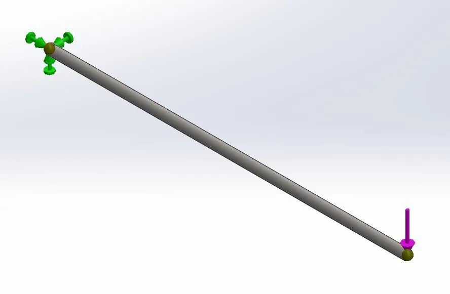
Figure 1: Fixture and load setup on the test body.
This case study used the following analytical equations.
Maximum Deflection:
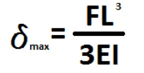
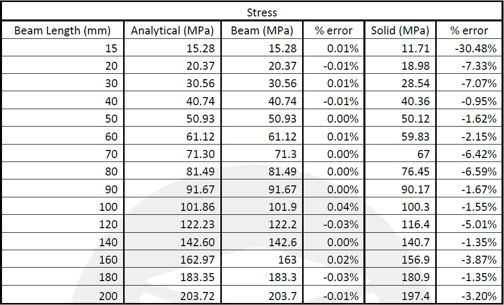
Maximum Stress:
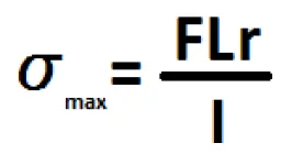
| Where: | F = Applied Force | = 100 N |
| L = Beam Length | = variable | |
| E = Modulus of Elasticity | = 2.1*1011 N/m2 | |
| I = Cross section Moment of Inertia | = 4.9087*10-10 m | |
| r = Cross sectional radius | = 5 mm |
Results
The results of the FEA testing and analytical calculations are shown below.
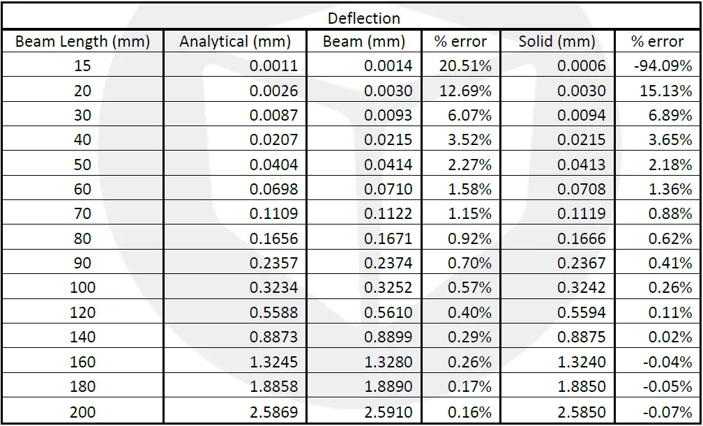
The beam-element deflection results agree with the analytical solution within 5% for length-span ratios greater than 4:1 and accurate within 1% for ratios greater than 8:1. The solid-element deflection results would agree with the beam deflection results.
The beam-element stress results are identical to the analytical solution (within < 0.5%) for all tested model lengths. The solid-element stress results vary largely across the range of results but remaining within 8% of the analytical solution.
Lastly, the solve time for the beam-element studies was < 0.01 seconds while the solid-element studies were solved in 10 seconds.
Conclusion
Beam elements have dubious accuracy for deflection below length-span ratios of 8:1. For stress calculations, beam stresses use the analytical calculation for stress, so the results would be the same. Solid elements show similar accuracies to beams for deflections but higher errors for stresses. Reduced the solid-element mesh size would compensate for this error. Solids can be trusted for length-span ratios of less than 8:1 where beam calculations and the analytical equations become invalid.
Beam elements, in this case, solve ~1000 times faster than solid elements. For larger, more complex beam structures, the inaccuracies from beam elements are offset by reduced design cycle and solve time.
Learn More about SOLIDWORKS Simulation Elements and Stress
Why Use Hex Elements in your FEA
Define Shell Elements by Selected Faces in SOLIDWORKS Simulation
SOLIDWORKS Simulation Nonlinear Material Models Stress-Strain Curves Explained
Time-Based Thermal Stress in SOLIDWORKS Simulation
Performing a Thermal Stress Analysis in SOLIDWORKS Simulation

About Ryan Dark
Ryan has been in the GoEngineer technical support team since February 2008 where he most notably provides support for all FEA and CFD software offered by SolidWorks. His most recent accolade is the title of Elite Application Engineer awarded by SolidWorks Corp.
Get our wide array of technical resources delivered right to your inbox.
Unsubscribe at any time.