Time Based Thermal Stress in SOLIDWORKS Simulation
Given that SOLIDWORKS Simulation is capable of running a transient thermal analysis on models it leads to the question of whether the transient temperatures of a model induce catastrophic stresses. Through the application of a Design Study, SOLIDWORKS is capable of calculating thermal stress values for each time step of a transient thermal analysis.
In this example setup, the filament of a light bulb is being heated with a 0.1 Watt source. All heat is being lost to radiation so the glass bulb and plug assembly can be removed to simplify the study and speed up the analysis. Further, thermal resistance is used between the wires and the filament to approximate a complex connection that might inhibit heat transfer and in this instance.
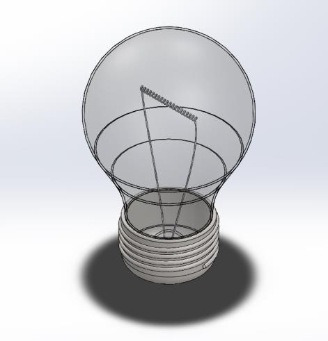
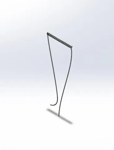
Figure 1: The original bulb model is shown on the left with the simplified analysis model of only the filament wire shown to the right
Create and Run the Transient Thermal Study
This transient thermal study contains 3 bodies (2 wires and 1 filament) adjoined with “Thermal Resistance” contact sets. The thermal loads applied to the model are an initial temperature of room temperature, a heat power, and a radiation definition with an ambient temperature set to room temperature. The thermal study boundary tree will look similar to Figure 2.
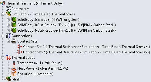
Figure 2: Thermal study boundary tree showing radiation cooled setup for the filament
Running this study should give temperature results for all time increments that will then feed into a static study.
Create the Static Study
The static study still contains all three previous bodies adjoined with “Bonded” contact sets. The free ends of the wires, where they connect to the plug contacts are fixed and the only load applied is a “Thermal Effects” load that transfers the temperature results from the thermal study to run a thermal stress analysis. The static study boundary tree will look similar to Figure 3.
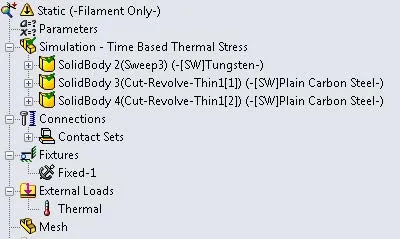
It is not important to run the static analysis but you will return to this static study to link a parameter from the Design Study.
Create and Link the Design Study
Having a transient thermal and static study set up the operation to use them in conjunction with each other to obtain stress results at each time step will be to use a Design Study. The exact process will go as follows:
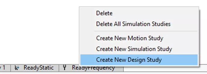
- Right-click on a ‘Study’ tab at the bottom of the screen and select ‘Create New Design Study’.
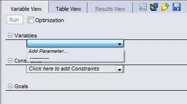
- On the new ‘Design Study 1’ tab select ‘Click here to add Variables’ then ‘Add Parameter’.
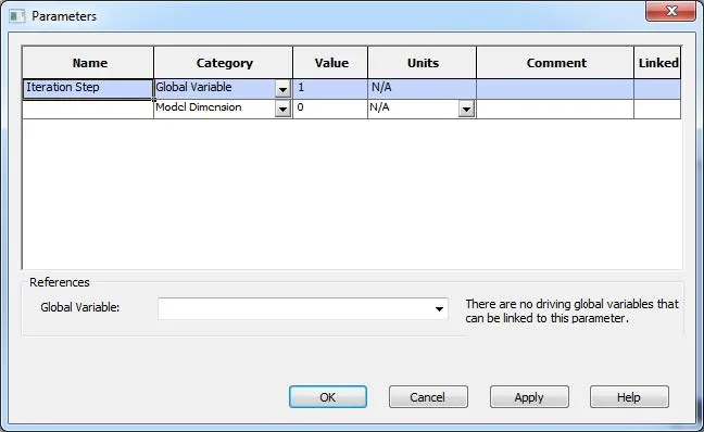
- Create a new Parameter named “Iteration Step”, set the category to ‘Global Variable’ then enter a value of “1”.
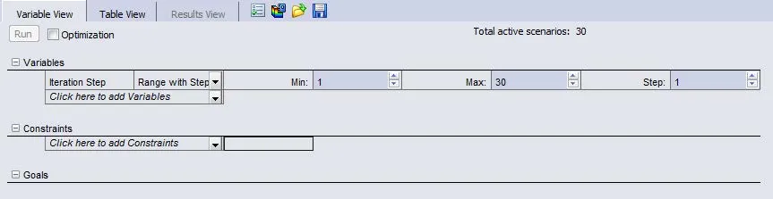
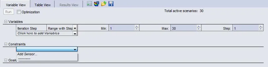
- Set the ‘Variables’ settings for “Iteration Step” to ‘Range with Step’ then enter minimum values of “1” and a maximum value corresponding to the total number of time steps the transient thermal analysis has (in this case the example has 30 steps), and use a step size of “1”.
- With that parameter created it now needs to be linked within the static study so the Design Study can iterate through all the thermal time steps. In the static study, right mouse click on the ‘Thermal’ load and go to ‘Edit Definition’.
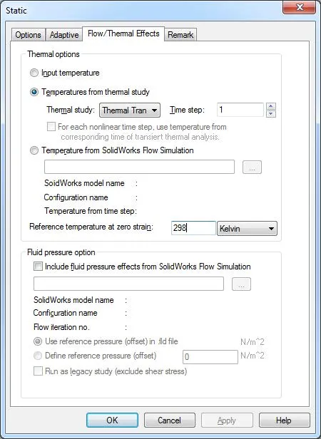
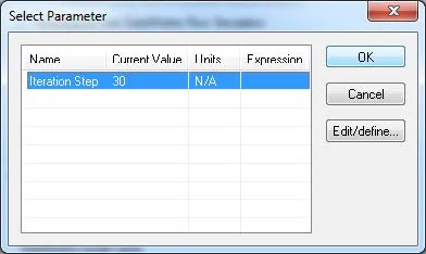
- Right-click on the number in the ‘Time step’ field and select ‘Link Values’. In the ‘Select Parameter’ dialog select “Iteration Step” and press ‘OK’ then press ‘OK’ to the thermal effect definition.
- Once the parameter is linked in the static study go back to the Design Study to complete the ‘Constraints’. Select ‘Click here to add Constraints’ then ‘Add Sensor’.
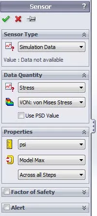
- The sensor settings are important as they are the numeric value being collected from each time step of the thermal/static analysis. In this case, a simple collection of the ‘Model Max’ stress value will be collected with the settings as noted in the image below:
- Once the sensor is created set it to ‘Monitor Only’ and see that it has already selected the static study due to the link parameter.
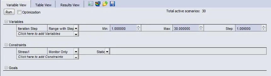
- The final step is to click ‘Run’ and allow the Design Study to proceed.
Conclusion
The final result is a Design Study which reports the maximum stress value due to each time step of the transient thermal analysis as illustrated in Figures 3 and 4.
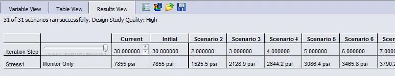
Figure 3: Design Study results showing values of stress for each thermal time step
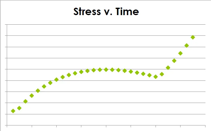
Figure 4: A graphed representation of Stress vs. Time from the Design Study results
Our Newest SOLIDWORKS Simulation Articles
Backspin is Important to your Basketball Free throw! A SOLIDWORKS Simulation Study
SOLIDWORKS Simulation Tips: No Penetration Contact Set Setup
A Guide for Bearing Connectors in SOLIDWORKS Simulation

About Ryan Dark
Ryan has been in the GoEngineer technical support team since February 2008 where he most notably provides support for all FEA and CFD software offered by SolidWorks. His most recent accolade is the title of Elite Application Engineer awarded by SolidWorks Corp.
Get our wide array of technical resources delivered right to your inbox.
Unsubscribe at any time.