SOLIDWORKS Simulation - Instability Diagnosis
Common Stability Errors in SOLIDWORKS Simulation
In cases where a SOLIDWORKS Simulation analysis produces solver errors (shown in Figure 1), like the ones shown below, it is likely that the analysis is unstable. These errors essentially all mean the same thing, namely that a body within the analysis is not fully restrained. An unrestrained body under load is capable of rigid body motion, or in a sense capable of “flying away”, which then causes the solver to fail. Rigid body motion is largely not allowed for Finite Element Analysis; typically this is because a large displacement leads to a divergent solution.
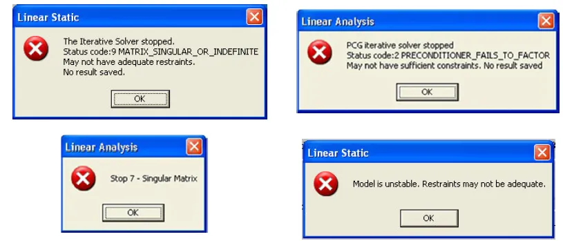
Figure 1: A sample of various errors given by SOLIDWORKS Simulation due to instability in an analysis.
Ultimately, the goal in a finite element analysis (FEA) is to ensure that all parts are restrained from rigid body motion in 3D space (where no translations or rotation are allowed in the X, Y, and Z directions) so bodies can be simulated in strained motions (i.e. bent in a virtual environment). These restraints are necessary in order to cause the bodies of the model to be bent rather than just pushed around in space. This is done in SOLIDWORKS using boundary definitions called “fixtures”. Fixtures are directly applied to bodies or are applied by association by defining a bonded “contact set” connecting bodies without fixtures to a body which a fixture is directly applied.
Instability errors occur when assumptions have been made about the bonds between bodies where the assumed restrictions do not truly restrict rigid body motion. This failure mode is seen most often when a multi-body analysis has a "global bonded" contact definition applied. The global contact definition relies on the program to automatically recognize coincident faces between bodies and then subsequently apply bonded contacts to these locations. Unfortunately, the application does not always recognize intended bond areas or geometric issues within the model, such as tiny gaps between faces, prevent the program from otherwise recognizing the bonded contact.
There are several methods to diagnose and repair these errors. Each method outlined in this article will present a way to locate unrestrained bodies so that the efforts to restrain them can be focused and a minimum amount of time is spent trying to locate unstable bodies.
Method #1: “Soft Springs” Applied in Static Analysis
To use this method, start by duplicating the unstable study (henceforth referred to as “Unstable”), labeling the duplicate “Gravity Test”. This is so that the integrity of the load, fixture, and contact definitions of the Unstable study are maintained while the Gravity Test study is allowed to undergo modifications. In this new Gravity Test study the basic setup should be as follows:
- Mesh Types: Unchanged from the Unstable study
- Material: Select a single arbitrary material from the SOLIDWORKS Material to apply to all bodies
- Connections: Unchanged from the Unstable study
- Fixtures: Unchanged from the Unstable study
- External Loads: Remove all currently applied loads. Define a gravity load as a replacement
- Mesh: Unchanged from the Unstable study
In this way the Gravity Test study has all the same contact, connector, and fixture definitions as the Unstable study. The material and external loads definitions have been removed so that instabilities caused by soft materials, material model types, and overloading, that may cause excessive bending, can be ignored.
Now, under the study settings for Gravity Test the option for “Large displacement” should be left off while the option for “Use soft springs to stabilize model” should be turned on.
Once these options are set, run the Gravity Test study. In most cases the study will run without problems until the warning appears that cites “Excessive displacements were calculated in this model” (shown in Figure 2). At this point responding “Yes” will turn on the “Large displacement” option previously left off and the program will attempt to incrementally apply the load to the model. If the model were stable a solution might be found this way but if the model is unstable the solver will simply fail with no further details provided. Responding ‘No’ will allow any results that have been calculated thus far to be saved. These results will not be useful for FEA, but are intended to help locate where the model is experiencing excessive displacement presumed to be rigid body movements of unstable bodies.
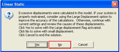
Figure 2: A warning caused by excessive displacements that could be due to rigid body motion.
After selecting “No”, activate the “Displacement” plot in the list of results. Once active, right click on the plot name and go to ‘Edit definition’ for the plot. The ‘Deformed Shape’ option is active by default but, for troubleshooting purposes, should be turned off. The deformed shape option is turned off because some parts may experience large displacements to such a degree that they will not be visible near the restrained portion of the model. By deactivating the ‘Deformed Shape’ option the plot will show a simple color gradient of displacements. When looking at the newly changed Displacement plot most of the model will likely be blue while some bodies will show in red (shown in Figure 3). The red color indicates large displacement highlighting suspect bodies that may need additional fixture or contact definitions to be restrained.
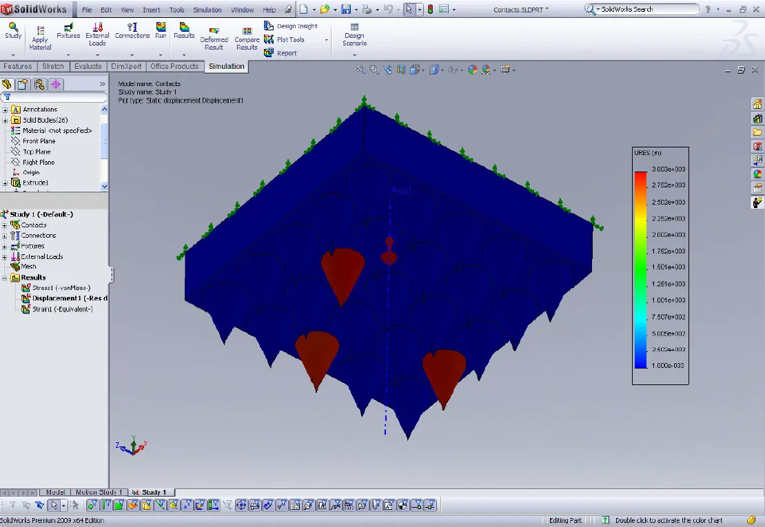
Figure 3: Displacement plot with deformation turned off showing several unstable (red) bodies.
Having identified which bodies are experiencing excessive displacement the next step is to apply a ‘Fixture’ item or, more commonly a bonded ‘Contact Set’ between the unrestrained body and an adjacent stable body. Apply whichever best suits the situation, and re-run the study. This procedure is an iterative process and may have to be performed several times before all the problem areas are all properly restrained.
Method #2: Observe Rigid Body Modes of a Frequency Analysis
To use this method, start by creating a brand new frequency-type study and label it “Frequency Test”. Copy all of the connection and fixtures definitions from the original (henceforth known as “Unstable”) study into the new Frequency Test frequency study. This, again, is so that the integrity of the load, fixture, and contact definitions of the original study are maintained.
If the Unstable study contains connections or contacts that cannot be defined in a frequency study (bolt connections, no penetration contacts, etc) these should be then replaced by bonded contacts at these interfaces to ensure ongoing stability at these locations. Additionally, no loading should be applied in the Frequency Test study as unrestrained bodies will be shown through rigid body motion seen in each mode shape plot. In this new Frequency Test study the basic setup should be as follows:
- Mesh Types: Unchanged from the Unstable study
- Material: Unchanged from the Unstable study
- Connections: Bolt connectors and No Penetration contacts replaced by Bonded contact sets
- Fixtures: Unchanged from the Unstable study
- External Loads: No applied loads
- Mesh: Unchanged from the Unstable study
Some study properties should be set as well before running the study (shown in Figure 4); “Use soft spring to stabilize the model”. Additionally the solver type should be set to ‘Direct Sparse’ as the ‘FFE Plus’ solver will fail to solve when there is a mix of fixed/bonded/stable bodies and unfixed/free/unstable bodies.
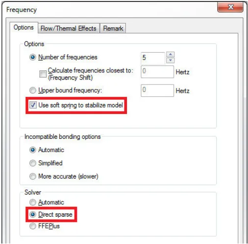
Figure 4: Frequency stability setting found under the frequency study properties.
The benefit of this method is given relatively little setup the study can be set to run and give results that show which bodies are unstable. If the study has an unstable body the natural frequencies of the first few modes should be close to zero; this confirms rigid body modes or a body that would be unstable in other study types.
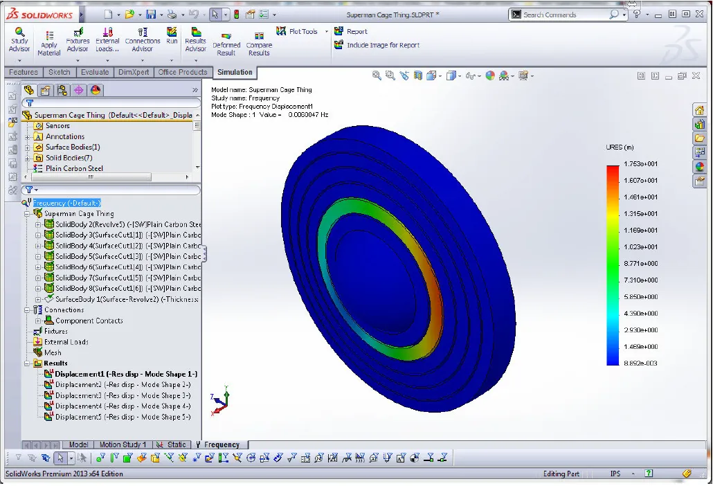
Figure 5: A mode shape plot showing an unstable body in a frequency study.
If the model is not complex a frequency study can be run relatively quickly to yield frequency mode plots that visualize the rigid body motions of the assembly being analyzed. Figure 5 shows such a result plot showing that one of the rings in this setup is unstable.
Method #3: Build the study from the “ground” up.
To use this method, start by duplicating the unstable study (henceforth referred to as “Unstable”), labeling the duplicate “Build Up”. This is so that the integrity of the load, fixture, and contact definitions of the Unstable study are maintained while the Build Up study is allowed to undergo modifications. In this new Build Up study the basic setup should be as follows:
- Mesh Types: Unchanged from the Build Up study
- Material: Select a single arbitrary material from the SOLIDWORKS Material to apply to all bodies
- Connections: To be discussed below
- Fixtures: To be discussed below
- External Loads: Remove all currently applied loads. Define a gravity load as a replacement
- Mesh: Unchanged from the Build Up study
This third and final method is somewhat a “brute force” approach to solving instability errors but at times can be the most constructive. All Connections and Fixtures are removed at first; they will be added back into the Build Up study on an as needed basis. All loads will also be removed and replaced by gravity so that each body is under load but specific loads do not need to be applied while going through this process.
This approach entails first excluding all the bodies within the analysis tree (via right mouse clicking on listed bodies and selecting “Exclude from Analysis”); if the study were left this way it would mean there are no bodies to analyze. Following this, the first body to be included again (via right mouse clicking on the listed body and selecting “Include in Analysis”) should be the base body that will be attached directly to a fixture. Include the base part and attach the fixture. At this time, run the study to test for stability; the model should be stable considering a fixture has been directly applied.
Following a successful test run of the study (it returned results expected for a gravity load applied to a stable study) adjacent bodies to the base body should now be included in the analysis. With the addition of these bodies bonded ‘Contact Sets’ should be defined that explicitly bond faces of the adjacent bodies to faces of the base body. Once contact sets are all defined for the new included bodies run the study to test for stability. At this point, one of two things will happen:
- The study with the new included bodies (and ‘Contact Sets’) will be stable and give results fitting a gravity load
Or
- The study will not be stable and give an error
In the case where the study is still stable with the newly included bodies more adjacent bodies may now be included in the analysis along with bonded ‘Contact Sets’ to attach them to the previous setup. In the case where there is a stability error, the ‘Contact Sets’ defined on the newly included bodies should be revisited followed by another test run of the study. When the study is able to solve and is stable the process may then be iterated by adding more adjacent bodies with more bonded ‘Contact Sets’ then the study run to test stability.
In this method the structure is figuratively being built up from a stable “ground” and tested at each stage of development to ensure stability.
Tips for stable studies
Symmetry Fixtures: Use ‘Symmetry’ fixtures wherever appropriate and possible. If a model has a plane of symmetry or has circular symmetry that model is more stable when it is cut in half (or into a wedge) and symmetry is applied. For example a bilaterally symmetric model when cut in half and symmetry is applied to the cut face will be more stable than the model left whole. When non symmetric forces are applied however, this may not be possible.
2D Simplification: Making use of ‘2D simplification’ can remove the need to stabilize 2 rotational and 1 translational rigid body motion of a model (out of a total of 3 rotational and 3 translational rigid body movements). This leaves only 2 translational and 1 rotational rigid body movements to stabilize; this can be much easier than trying to stabilize the 3D model.
Use ‘Contact Sets’: While Global and Component contact definitions can be very fast and easy to set up they only work when bodies share coincident faces (sometimes not even then). If there is any doubt as to whether contacts are correctly defined use a ‘Contact Set’ instead. ‘Contact Sets’ while more detailed and time consuming are as near to a “sure thing” as contacts get.

Related content
Tank Sloshing Using SOLIDWORKS Flow Simulation
Managing SOLIDWORKS Simulation Results with PDM
7 Steps to Perform a Fatigue Analysis in SOLIDWORKS Simulation

About Ryan Dark
Ryan has been in the GoEngineer technical support team since February 2008 where he most notably provides support for all FEA and CFD software offered by SolidWorks. His most recent accolade is the title of Elite Application Engineer awarded by SolidWorks Corp.
Get our wide array of technical resources delivered right to your inbox.
Unsubscribe at any time.