SOLIDWORKS Simulation Solution Adaptive Mesh Refinement
Meshing plays an important role regarding the accuracy of a SOLIDWORKS Simulation analysis. The linear static study module includes an option that allows for the solver to adapt the mesh during the solution in regions of the model with high strain energy errors. This results in a more accurate solution with little user input.
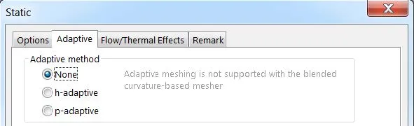
There are two types of solution adaptive mesh refinement methods that can be used: h-adaptive and p-adaptive. This guide will cover the differences between the two methods and how to enable them.
Accessing the Adaptive Methods
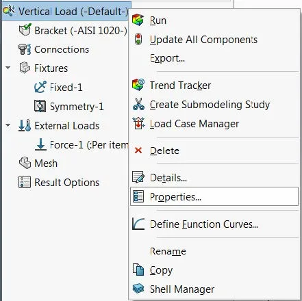
The solution adaptive mesh refinement methods can be enabled from within a linear static’s study properties dialogue, which can be accessed by right-clicking on the name of the study at the top of the linear static study tree.
The two solution adaptive mesh refinement methods are located on the Adaptive tab.
H-adaptive
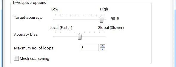
The h-adaptive mesh refinement method automatically reduces the element size in areas of high strain energy norm error. The Target accuracy slider bar sets the desired error for the solution. The default value of 98% specifies that the solution will stop when the strain energy norm error in the model is less than 2%. This slider bar can be set to 99%.
The Accuracy bias slider bar controls how mesh refinement will be specified in the model. Moving the slider bar towards Local (Faster) will instruct the solver to concentrate on getting accurate peak stress results using a fewer number of elements.
Moving the slider bar towards Global (Slower) will instruct the solver to concentrate on getting overall accurate results. Stress singularities occur at locations of concentrated forces and sharp corners. The stress results in these locations will keep increasing as smaller elements are used. It is recommended to move the slider bar towards Global (Slower) for models with such singularities.
The Maximum no. of loops option sets the maximum number of solutions loops allowed when the study is run. The maximum number of loops that can be specified is 5.
The Mesh coarsening option can be selected to allow the solver to reduce the number of elements (increase the element size) in regions of the model with low strain energy norm errors. With this option unselected, the number of elements in the model will continually increase with each subsequent solution loop.
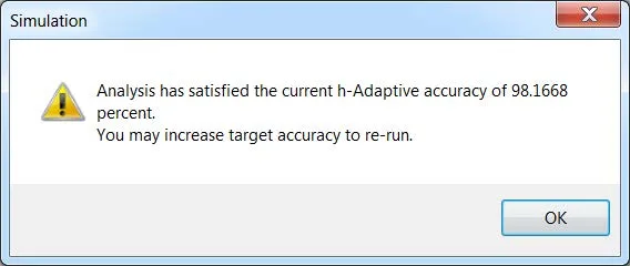
The solution will stop when either the target accuracy has been achieved or the maximum number of loops has been reached. A message will appear if the target accuracy has been achieved. If a message does not appear, that means the maximum number of loops has been reached. In this case, the study can be run again and the mesh adaptive refinement process will pick up where it left off in the last loop.
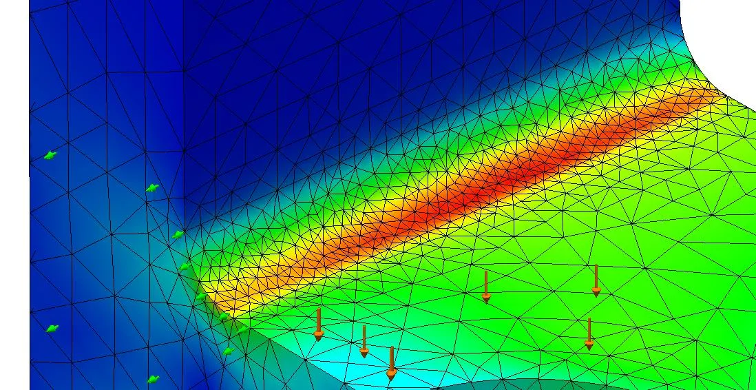
The following image displays a stress plot with the mesh overlaid. The solver adapts the mesh exactly where it is needed based on the locations of high strain energy norm error.
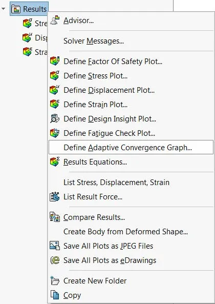
An Adaptive Convergence Graph can be defined by right-clicking on the Results folder.
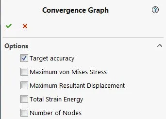
This graph allows for plotting different attributes versus the number of solution loops. Target accuracy, maximum von Mises stress, maximum resultant displacement, total strain energy, and number of nodes can be plotted.
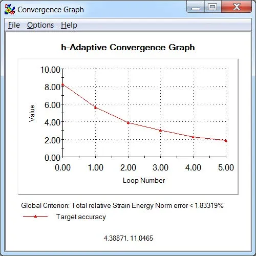
The convergence graph starts at loop 0 (first loop). The following h-adaptive convergence graph indicates that the solution reached its target accuracy of less than 2% in 6 loops.
P-adaptive
The p-adaptive mesh refinement method uses more efficient elements in regions of high strain energy errors. The mesh doesn’t change, but the order of the element increases. What this means is that the order of the polynomial equation used to approximate the displacement field increases to achieve a more accurate solution for a given element size (volume).
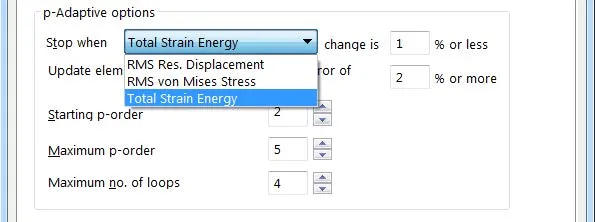
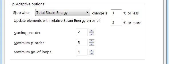
The Stop when _ change is _ % or less condition indicates when convergence has been achieved and looping stops. It sets the maximum allowable relative change in the selected global criterion. The criterion can be set to three different options:
- RMS Res. Displacement: The Root Mean Square value of the nodal resultant displacements.
- RMS von Mises Stress: The Root Mean Square value of the nodal von Misses stresses.
- Total Strain Energy: The strain energy of the model calculated by summing the strain energy of all elements.
The Update elements with relative Strain Energy error of _ % or more condition sets the maximum allowable relative error in the strain energy of each element. If none of the other two stopping criteria are met, the program will increase the polynomial order of the elements with strain energy of _ % or more.
The Starting p-order condition sets the order to be used for the first loop. It can be set between 2 and 5 (2 represents a second order element and 5 represents a fifth order element).
The Maximum p-order condition sets the maximum order of the element. The highest possible order can be set to 5.
The Maximum no. of loops condition sets the maximum number of loops allowed in the solution. The maximum possible number of loops is 4 (if starting p-order is set to 2 and the maximum p-order is set to 5).
The program stops the loops when one of the following conditions is met:
- The global criterion converges
- All local errors converge (i.e., for each element)
- The maximum number of loops is reached
If the maximum number of loops is reached and the other two terminating conditions have not been met, then an initial finer mesh would have to be created and the solution adaptive mesh refinement process would have to be restarted.
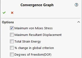
An adaptive convergence graph can be created when using the p-adaptive method. The attributes that can be plotted versus the number of solution loops are a little bit different than for the h-adaptive method. Maximum von Mises stress, maximum resultant displacement, total strain energy, % change in global criterion, and degrees of freedom (DOF) can be plotted.
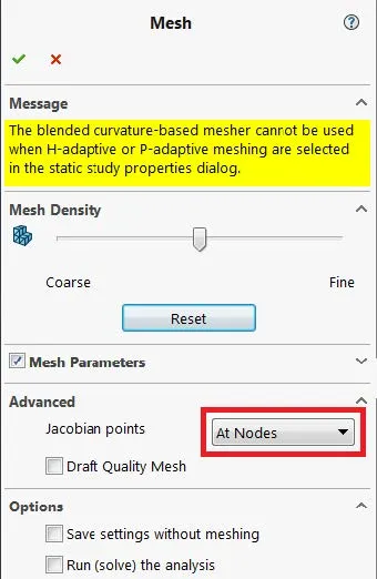
It is recommended to select the At Nodes option under the advanced section of the global mesh dialogue window when using the p-method to solve linear static problems.
Related SOLIDWORKS Simulation Tutorials
How Do I Know My Mesh is Good Enough?
Avoiding Singularities in SOLIDWORKS Simulation
SOLIDWORKS Simulation Results Export Options
SOLIDWORKS Simulation Gauss Points, Nodal, and Element Stress
Troubleshooting SOLIDWORKS Simulation No Penetration Contact Sets Recoommendations
![]()
About GoEngineer
GoEngineer delivers software, technology, and expertise that enable companies to unlock design innovation and deliver better products faster. With more than 40 years of experience and tens of thousands of customers in high tech, medical, machine design, energy and other industries, GoEngineer provides best-in-class design solutions from SOLIDWORKS CAD, Stratasys 3D printing, Creaform & Artec 3D scanning, CAMWorks, PLM, and more
Get our wide array of technical resources delivered right to your inbox.
Unsubscribe at any time.