Faster DWG Conversions Using the SOLIDWORKS 2D to 3D Toolbar
GoEngineer's Technical Support team is often asked how to convert 2D files to 3D SOLIDWORKS models. Whether legacy data from a previous CAD package or new customer data delivered in an inconvenient format, the need to convert it is the same. There are several ways to accomplish this conversion, but the 2D to 3D toolbar is purpose-built for the task. This article walks through how to use this often overlooked set of tools to import the model, transition and align the views, and then use that information to build a 3D model.
Import 2D Data as Sketches
- First, get your 2D data into SOLIDWORKS. For this example, I will File > Open a DWG file, which launches the DXF/DWG Import utility.
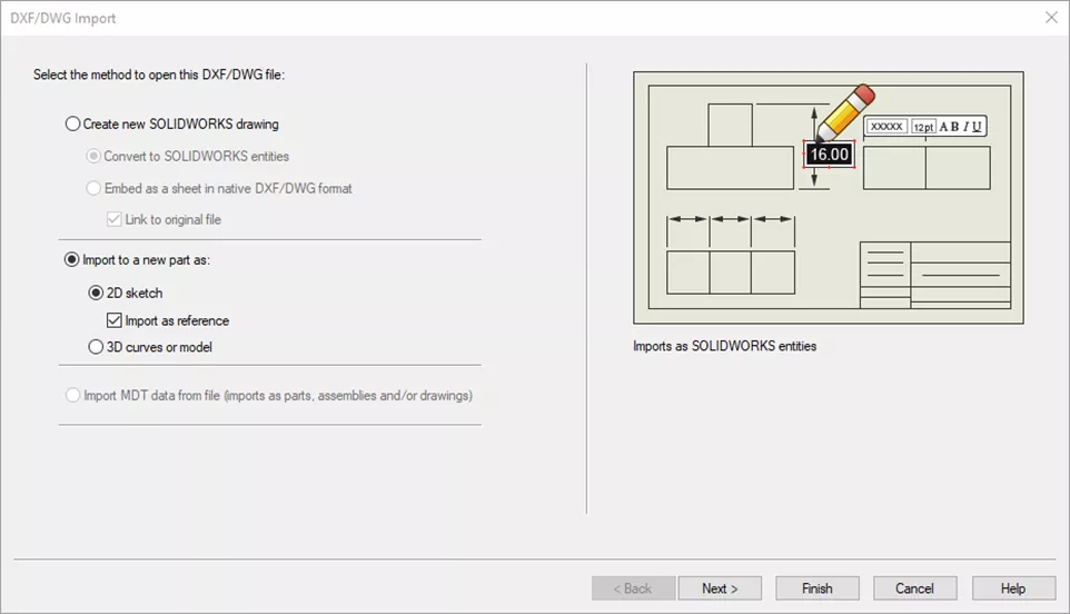
- On the DXF/DWG Import page, choose Import to a new part as and select Next (this adds the DWG geometry as a 2D sketch, imported as reference geometry, by default).
- Choose the appropriate units, whether you want constraints to be automatically added, dimensions imported, and which layers to import. For this example, I will set the units to Millimeters, turn off Constraints and Dimensions, and turn off all but Object and DIM layers. Select Next.
Note: Be careful not to turn off geometry that you need. It's not uncommon for items to be on incorrect layers.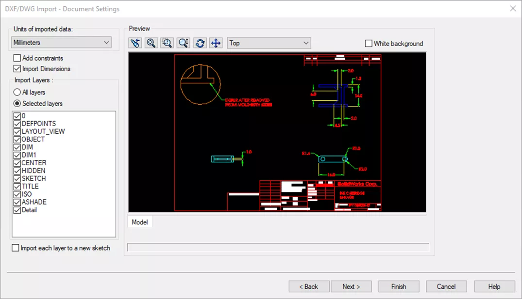
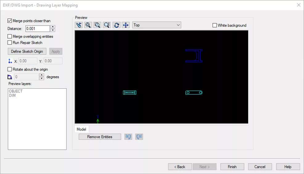
- Choose whether to automatically merge nearby points and overlapping entities, define an origin and global rotation if desired, and manually remove any unneeded entities. Then select Finish.
Note: If you receive a warning about Exploding Blocks, don't worry! Select the option that works best for what you want to do with your 2D data. Yes works best for the simple geometry in this example.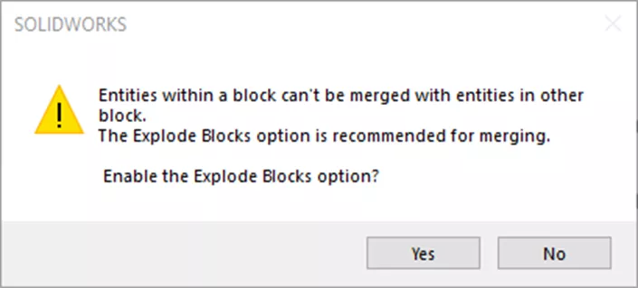
- A new part file will open, with the sketch locked as a Reference Sketch, and the 2D to 3D Toolbar active (usually attached to left toolbar, or floating as in this example).
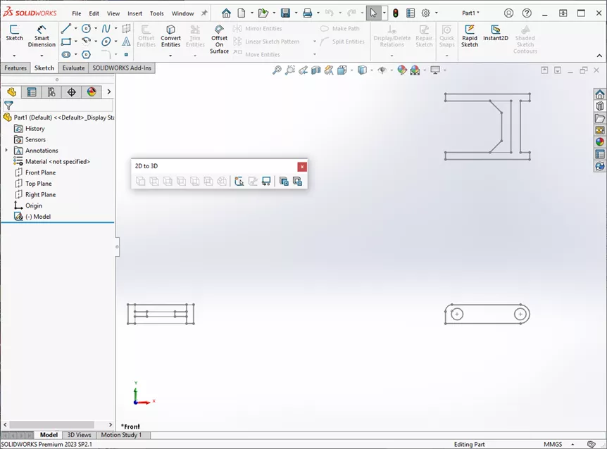
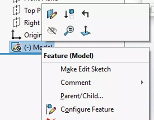
- Set the Sketch to be editable by right-clicking on it and selecting Make Edit Sketch.
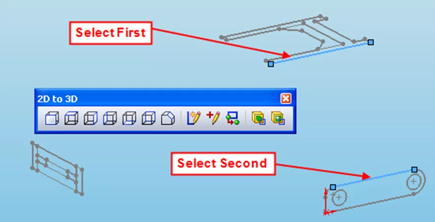
- Align the Sketch to the Origin of the part. Select a point you want at the origin and choose the Align Sketch button from the 2D to 3D Toolbar.

- With the geometry aligned, select the sketch geometry that should be on the Front view and select Add to Front Sketch from the 2D to 3D toolbar.
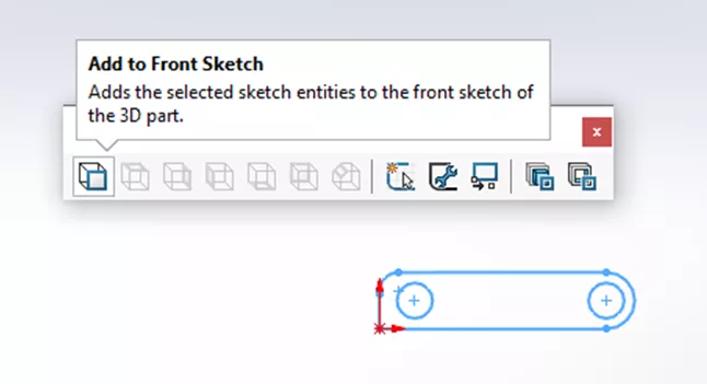
- Do the same for the Left and Top Views, using their respective buttons. These new views will rotate into their appropriate position.
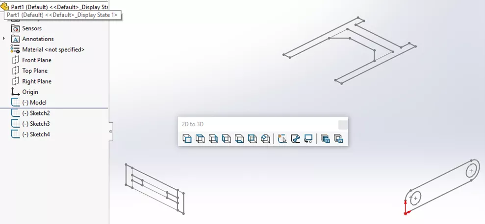
- The new views need to be aligned to the Front view. Select an edge from each view and use Align Sketch to line them up.
Build the 3D Model
- Use the sketches to add features to create the 3D geometry. For this example, I'm using the Convert to Extrusion and Convert to Cut commands in the 2D to 3D toolbar.
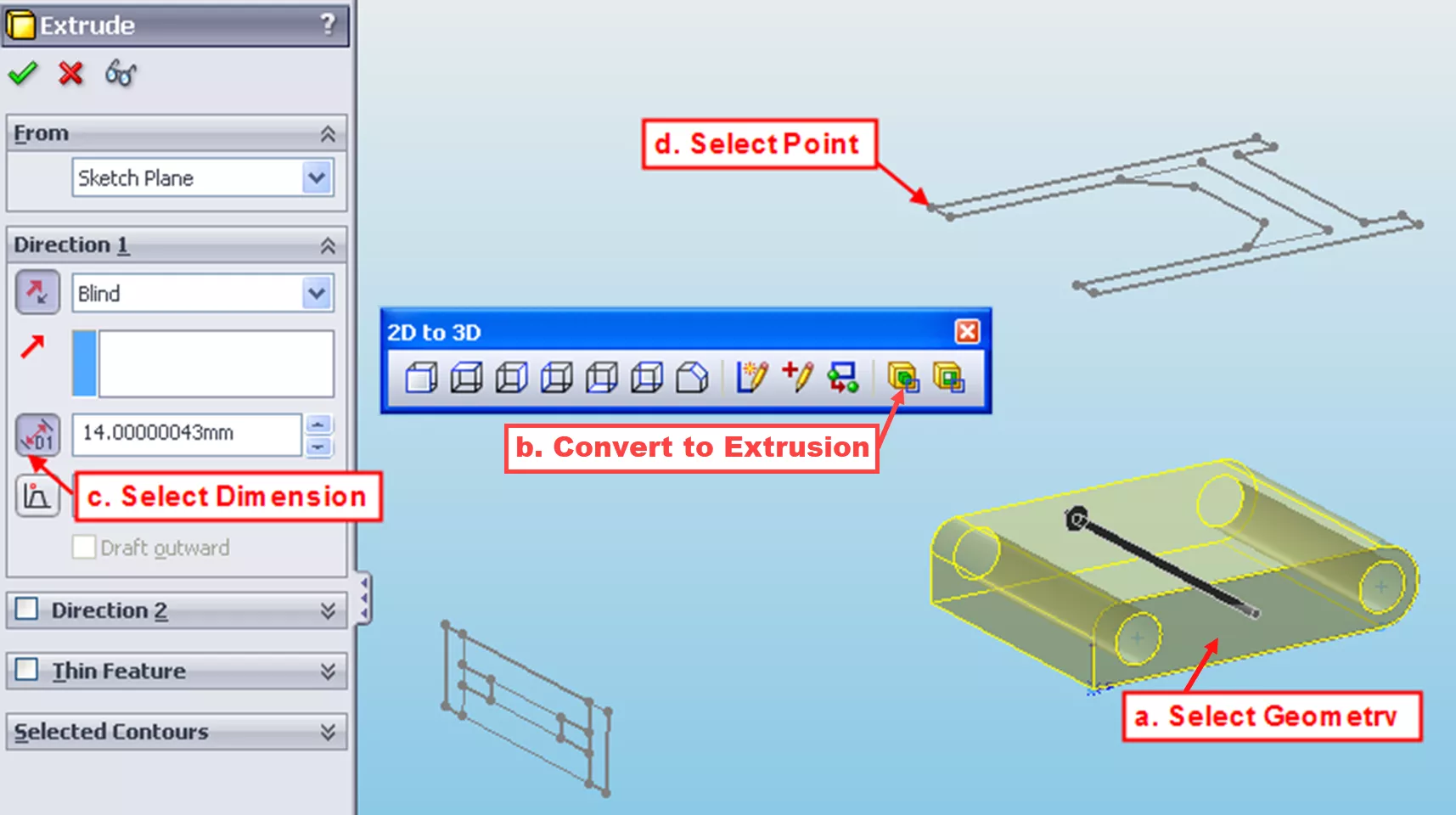
- Pre-select the sketch geometry to be extruded (right-clicking a sketch entity and using "select chain" can make selection easier). In this example, I've selected everything in the Front View.
- Use the Convert to Extrusion tool to define the direction of the extrusion.
- Define the depth of the extrusion by clicking the icon next to the depth/distance value...
- ...and then selecting a sketch vertex to end the feature.
- Remove unneeded geometry with Cuts
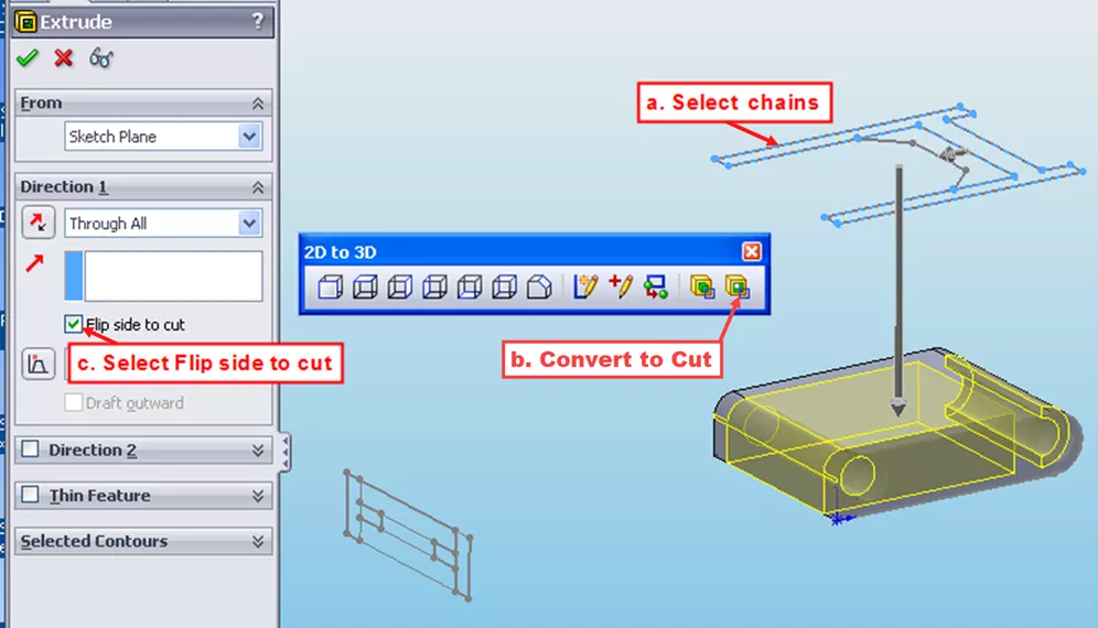
- Select Sketch geometry to define the area to be cut.
- Use the Convert to Cut tool to define the direction.
- Flip side to cut removes everything outside the selected sketch geometry.
- Finally, add any additional details
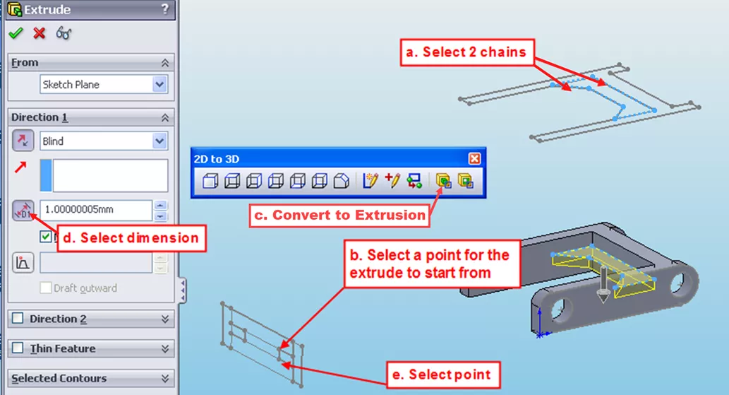
- Select the sketch geometry defining the cross-section of the feature.
- Select a sketch vertex to start the feature.
- Use the Convert to Extrusion tool to define the direction.
- Click the icon next to the depth value.
- Then, pick a vertex to define the end of the feature.
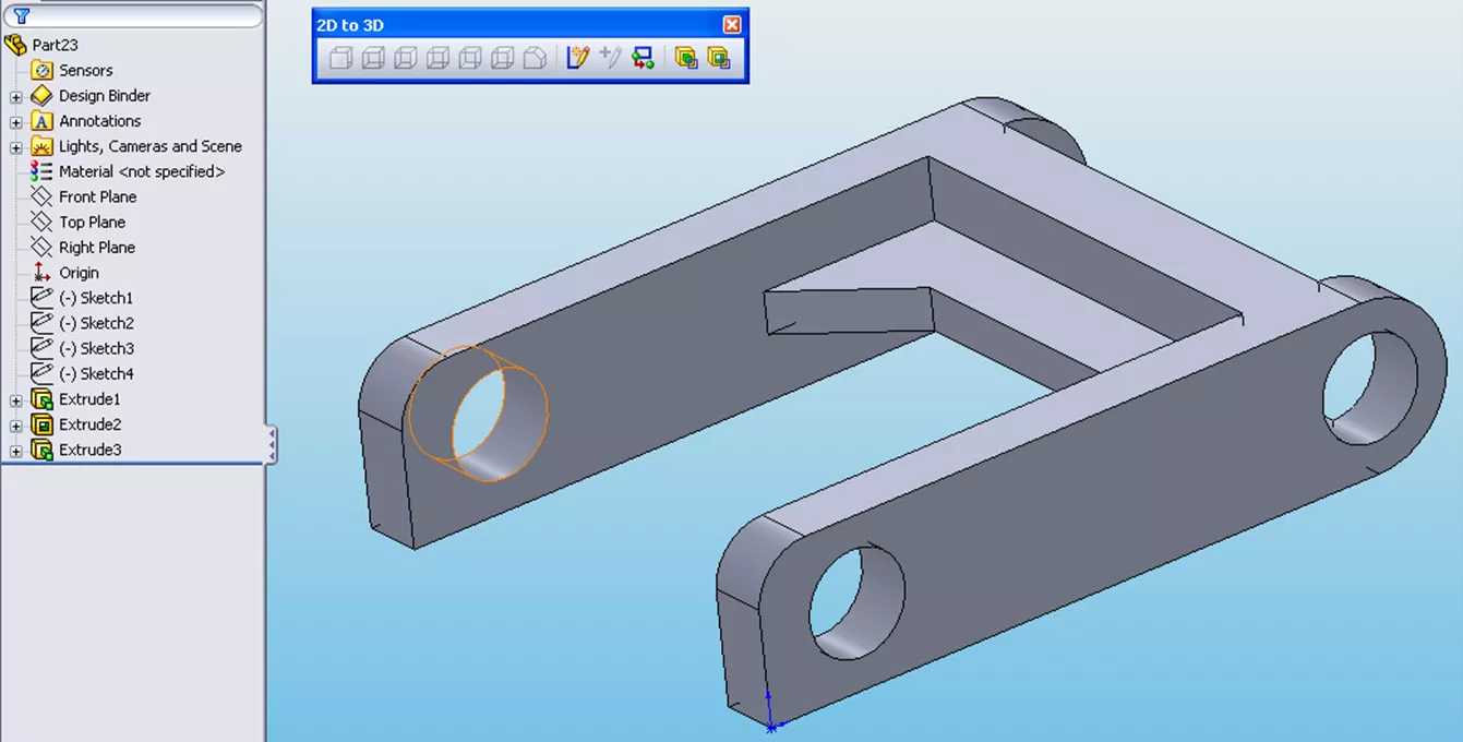
That's the completed part, made simpler, using the tools on the 2D to 3D toolbar!
Want to learn more? Check out more articles below. Additionally, join the GoEngineer Community to create forum posts, enter design contests, and answer questions from other SOLIDWORKS users.

SOLIDWORKS CAD Cheat Sheet
SHORTCUTS ⋅ MOUSE GESTURES ⋅ HOT KEYS
Our SOLIDWORKS CAD Cheat Sheet, featuring over 90 tips and tricks, will help speed up your process.
Related Articles
Create Custom Weldment Profiles in SOLIDWORKS
SOLIDWORKS Paragraph Properties Guide
Mastering Basic Part Modeling in SOLIDWORKS: A Step-by-Step Guide
Getting Started with SOLIDWORKS Hole Tables
![]()
About GoEngineer
GoEngineer delivers software, technology, and expertise that enable companies to unlock design innovation and deliver better products faster. With more than 40 years of experience and tens of thousands of customers in high tech, medical, machine design, energy and other industries, GoEngineer provides best-in-class design solutions from SOLIDWORKS CAD, Stratasys 3D printing, Creaform & Artec 3D scanning, CAMWorks, PLM, and more
Get our wide array of technical resources delivered right to your inbox.
Unsubscribe at any time.