SOLIDWORKS Electrical Design
simplify electrical design with Schematic, Circuitworks, PCB and more
SOLIDWORKS Electrical Design SOFTWARE
don't miss our upcoming webinar!
January 26, 2023 at 12pm PT
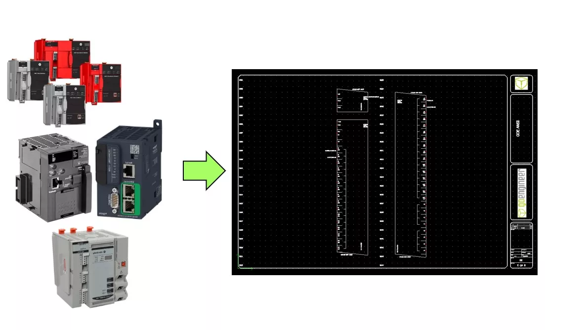
Creating Custom PLC Schematic Symbols
Join us for part 3 of our PLC series where we continue on our journey through PLCs. Creating Custom symbols can feel daunting especially since there is so much information you may want on the symbol. Where do you start? During this live webinar, we will walk through one of the easiest ways to get all your information in your symbols with the least amount of effort possible!
SOLIDWORKS Services:
Utilize GoEngineer’s Award Winning Support & Training for SOLIDWORKS
Award Winning Technical Support
GoEngineer's extensive SOLIDWORKS technical knowledge and world class support can help you succeed with SOLIDWORKS. Our award-winning team is ready to help you with any task you may have. Using state-of-art remote assistant technology software allows our team to solve most issues within one session. Reach out and see why GoEngineer is the #1 reseller of SOLIDWORKS and Stratasys systems in the world!
- 125+Certified Technical Specialists
- Email, Phone and Chat Support Available
- 98% Exceptional Customer Service Rating
PROFESSIONAL SOLIDWORKS TRAINING
GoEngineer offers online and classroom professional SOLIDWORKS training for organizations and individuals. All our instructors are SOLIDWORKS certified and teach thousands of students each year world wide. The curriculum is very diverse with numerous certified SOLIDWORKS courses to choose from. Each student will receive a Course Completion Certificate and preparation materials for SOLIDWORKS certification.
- Increase Your Earning Potential
- Led by Certified SOLIDWORKS Instructors
- Smaller Classes with Focused Attention
Additional Resources
Take Advantage of GoEngineer’s Extensive Knowledge Base and Resources

Find a Solution
Our robust Knowledge Base contains over 12,000 resources to help answer your product design questions. From basic CAD questions to in-depth guides and tutorials, find your solution here. Find a Solution

PROFESSIONAL TRAINING
Improve your skills with professional training and certifications in SOLIDWORKS, CAM, 3D Printing, and 3D Scanning offered four ways: self-paced, online, on-site, or in-classroom. Certified Training Courses

BLOG
#1 Technical Resource Worldwide - Right at your fingertips. Search or browse through hundreds of SOLIDWORKS tips & tricks, additive manufacturing product developments, announcements, how-to guides, and tutorials. Blog

YouTube Channel
Our YouTube channel hosts hundreds of educational tutorials, product demonstrations, recorded webinars, and best practices for all of our products and services. GoEngineer's YouTube Channel
ONLINE STORE
Order 3D printing materials and consumables, enroll in SOLIDWORKS training classes, and buy official GoEngineer gear directly from our online store. Online Store
WEBINARS
Our engineering webinars are hosted by some of the top experts in the industry. They are always recorded, always free, and always offer a live Q&A. WEBINARS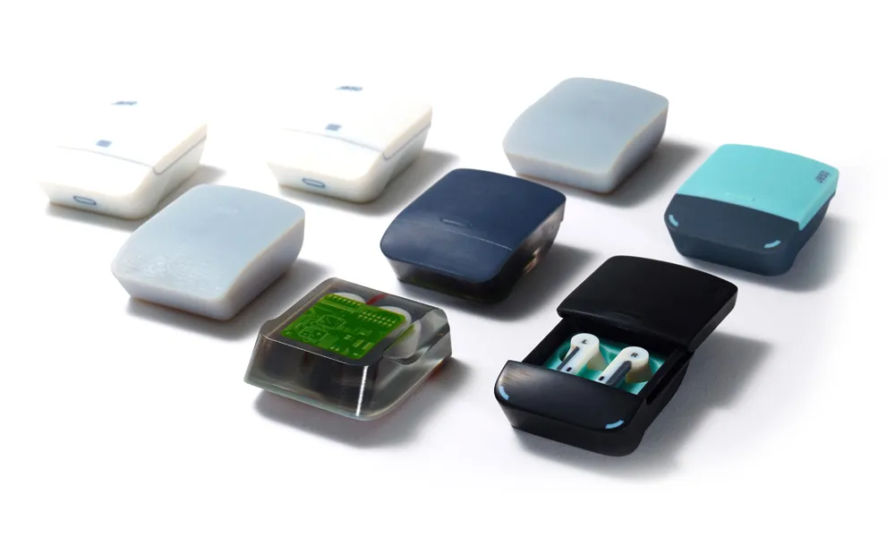
3D Printing Services
Need to 3D print a part? Our Additive Manufacturing experts will 3D print your part and deliver it to you using the latest technology on one of our professional FDM, PolyJet and SL 3D printers. 3D Printing Services