2 Ways to Reference a Cross-Section in SOLIDWORKS
Have you ever needed to pull a cross-section of a solid with the ability to trace it? SOLIDWORKS has two tools that simplify this task:
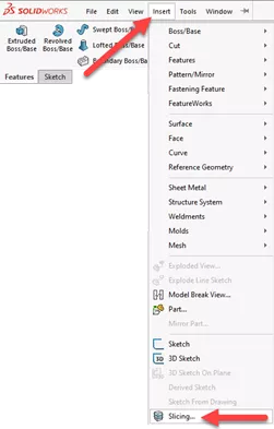
- SOLIDWORKS Slicing tool
- Intersection Curve
In this article, we'll look at both options and distinguish the differences between the two.
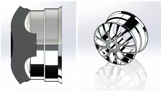
Below is an example of a part where we need to create a reference of the cross-section profile to design the spoke to the rim. The outer rim has been already designed, and the inner, solid body will fuse with the spoke afterward to create the counterbore holes.

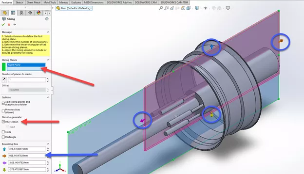
#1. Using the SOLIDWORKS Slicing Tool
The SOLIDWORKS Slicing Tool allows users to choose any plane as a reference and also choose the boundary to capture an area from within. Once finished, a new 2D Sketch of the enclosed thickness is generated. The boundary that’s visible acts as a filter that will capture all faces touching the boxed area. The SOLIDWORKS Slicing Tool also allows the addition of multiple planes but, in this example, just the right plane will do the trick.
Here we’ve chosen the plane where the intersection should be located. Checking the intersection box will allow the creation of the sketch. There's also the option to either drag the bounding box or enter the values to determine the boundary to capture.
When finished, a new 2D of the intersection will be created as a reference. The sketch will stay linked to the original geometry, whereas if the model geometry updates, so does the sketch that was created by the SOLIDWORKS Slicing Tool.

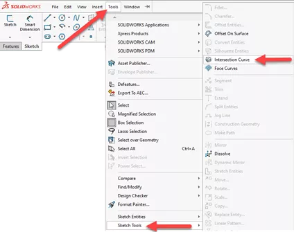
#2. SOLIDWORKS Intersection Curve
The Intersection Curve option in SOLIDWORKS offers a similar result, whereas multiple surfaces are selected individually. Unlike the Slicing Tool, all surfaces intersecting the plane will be projected, as opposed to just the area within the boundary.
Suggested Article >> SOLIDWORKS Intersection Curve Tool Explained
As with this example, we first created a new sketch on the right plane where the entities should intersect. Afterward, we selected the outer faces and a few of the inner surfaces to capture the necessary information.
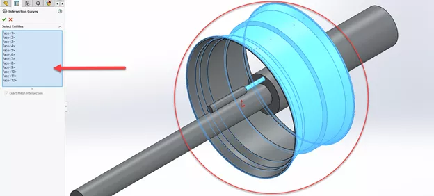
The sketch created by the Intersection Curve has a few differences but also contains the same relative information captured by the Slicing Tool.

Creating the sketch profile & spoke feature
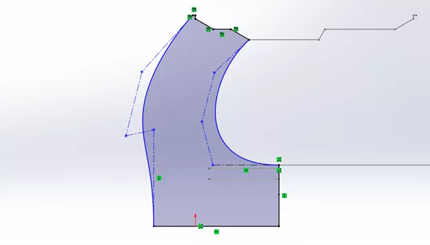
Once the profiles have been generated, either sketch can be used as a guideline for creating a spoke section. In this example, we chose the intersection curve sketch; below shows a profile that uses a combination of sketch relations and splines. Once done, the feature is generated and the rest of the spoke design can be carried out.
Slicing Tool vs. Intersection Curve: Which method is better?
As far as which command is more versatile, both can achieve the necessary references. It’s noted that the Slicing Tool offers an advantage due to the boundary and the option to add additional planes for multiple intersections. However, its current limitation is that planes are the only reference that can be used.
The intersection curve offers to ease of translating the entire surface boundary that crosses the plane. It can also do additional things like projecting intersections as a 3D sketch.
![]() For more, feel free to watch this video.
For more, feel free to watch this video.
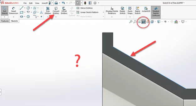
Why not just use the section view button?
While the Section View button is great for displaying the cross-section, it doesn’t offer the same versatility when it comes to referencing the model. As shown with the tools above, the information from the cross-section can be converted into visible sketches. Had we opted to work with the Section View command, some of the entities cannot be referenced or converted as easily as shown below.
I hope you found this article helpful. To learn more about SOLIDWORKS, check out the additional tips and tricks listed below.
More SOLIDWORKS Tutorials
Favorite SOLIDWORKS Tips from Tech Support
Creating and Adding Weld Beads in SOLIDWORKS Models & Drawings
SOLIDWORKS: Creating Normal Cuts in Sheet Metal
SOLIDWORKS: Splitting a Body into Multiple Parts

About Jackie Yip
Jackie Yip is a Technical Support Engineer at GoEngineer. When Jackie isn’t assisting customers or teaching a SOLIDWORKS Essentials class, he enjoys road biking and keeping up on the latest tech trends.
Get our wide array of technical resources delivered right to your inbox.
Unsubscribe at any time.