Change LeadIn and LeadOut Locations in CAMWorks
In this quick tip, we will cover how to change the leadin and leadout locations in CAMWorks.
What is a LeadIn or LeadOut?
A leadin or leadout is a control of how the tool will enter its cut. For example, if no leadin/out is applied, the tool will plunge straight down into position for the cut.
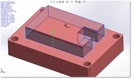
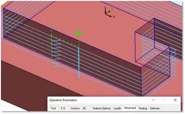
In the center of this boss feature is a bright green target which is the location of our leadin, and it plunges in a straight line to start its path. We have quite a bit of control when it comes to adjusting the position or changing the type of leadin or leadout.
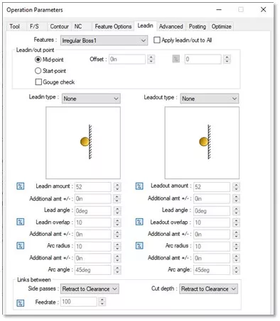
As you can see, the leadin is currently set to none.
The leadin/out is controlled by the LeadIn type and LeadOut type dropdown menus. In this example, the reason it's plunging is due to the type being set as none.
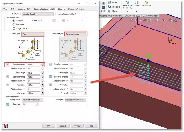
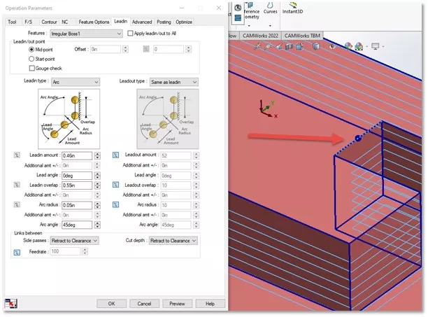
If we wanted to do an arc type leadin, we can set the drop down to arc and set our leadout type to same as leadin, so it follows. You can see it creates an arcing motion.
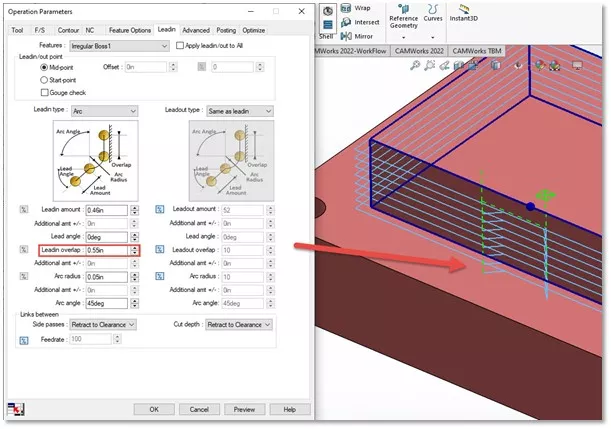
Adding some leadin overlap will space out your leadin so that its not so close together. You can do so with the option shown here.
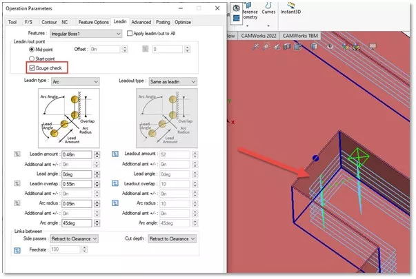
So how do we go about moving that leadin/out to a different point on the boss? One feature that can be difficult to notice on your own and can take a keen eye is that when in the Leadin tab, the profile of the boss will become bold.
In the first image, a different tab is selected and will look like the standard profile. In the second, the Leadin tab is selected, and the profile is bold.
Compare the two images and see the difference.
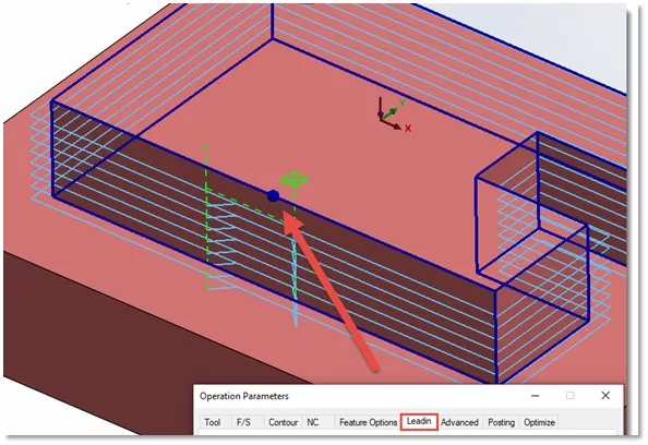
In the second image there is a bold blue dot. That is going to be the start position of our leadin.
In the example above, this one is set to mid-point. Mid-point means that it will calculate the middle of the line segment that it's currently applied to and place the leadin there.
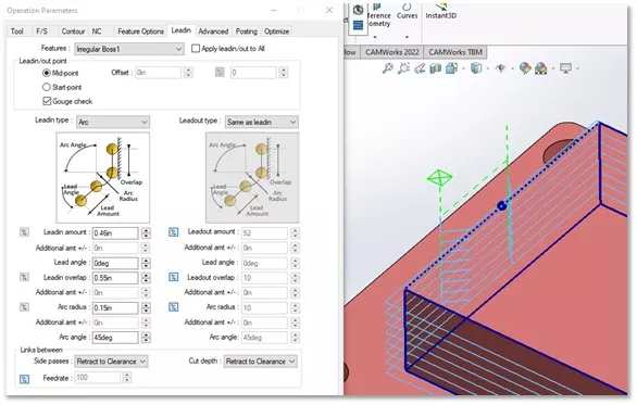
When the bolded lines are active, we have the option to move our leadin to a whole new segment by simply selecting another segment. You will see the blue dot move - once you hit preview to generate the toolpath, the leadin will move.
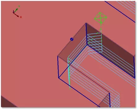
You may now notice that the tool will be running into the walls of the part. This is called gouging. To correct this, we can select the Gouge check option to adjust the path.
If we want to move to another segment, all we have to do is select a new segment line and select preview again.
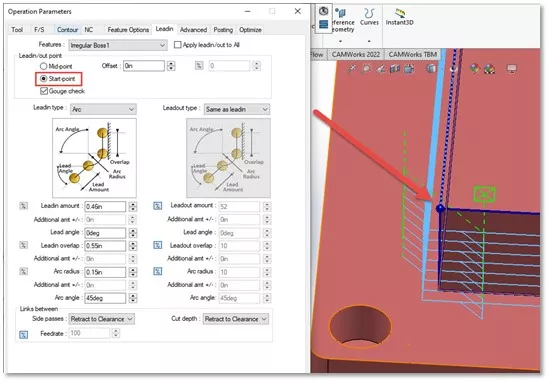
If you don’t want to enter on the mid-point of the segment, you can select the option for Start point. By default, with a zero offset applied, the start point will be the end of a segment.
If we apply an offset, you can see that the position of the blue ball moves by the distance that we have set. This value can be a numerical value or a percentage. In this example, I’ve offset it by one inch.
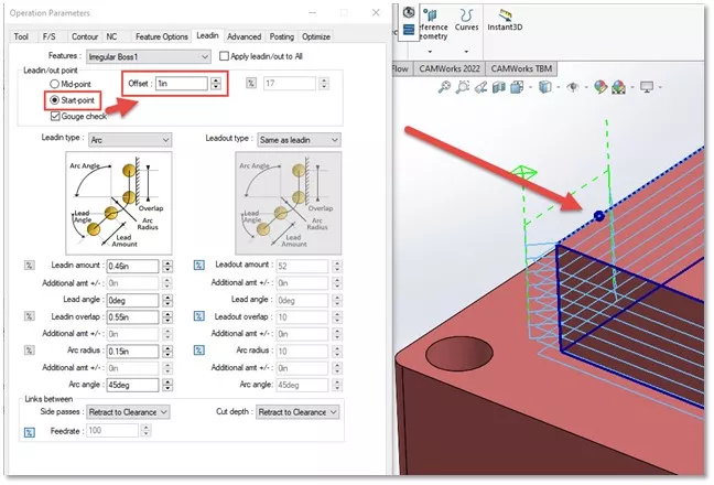
This is how we can control the leadins and leadouts of our boss and pocket type features. I hope you found this tutorial helpful. Check out more CAMWorks tutorials listed below.
![]() Want to see these same concepts in action? Check out our YouTube video.
Want to see these same concepts in action? Check out our YouTube video.
Learn More about CAMWorks
How to Create a Tool Crib in CAMWorks
CAMWorks Air Segment Offset Explained
How to Set Up a Firewall Exception for CAMWorks Teksoft.exe
Add Materials to CAMWorks Material Library
![]()
About Nick Stanley
Nick Stanley is a SOLIDWORKS Technical Support Specialist at GoEngineer.
Get our wide array of technical resources delivered right to your inbox.
Unsubscribe at any time.