How to Create an Extrude-Cut on a Curved Surface in SOLIDWORKS
Sometimes you will find yourself in a situation where you need to create an extrude-cut on a curved surface. People new to SOLIDWORKS get freaked out just at the thought of tackling such a complex endeavor, but it's not as difficult as it seems.
This tutorial will walk you through step-by-step the process of how to create an extrude-cut on a curved surface in SOLIDWORKS and offer a few quick tips along the way.
Let's use the following part as an example:
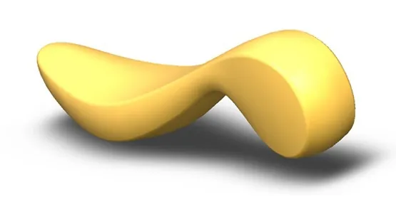
There is not a single flat face on this part (other than the three primary planes) on which to base a classic 2D sketch for your cut.
The challenge is to create a blind cut into the model and have the bottom face of the hole maintain the shape of the original face before the cut. For now, we will assume no draft is necessary.
At this stage, there are questions we need to answer before proceeding:
- What direction does the cut need to be in?
- Does the cut need to be perpendicular to one of the primary planes of the part?
- Do you need the cut to be a cut into the model with a blind depth?
- Does the cut need to have draft?
- Does it go ‘through all’?
Answering these questions will help frame the proper technique to use.
There are many approaches to a part like this. Here we will focus on using commands other than extrude-cut to get the job done.
First, let’s get the outline of the cut etched onto the face of the model.
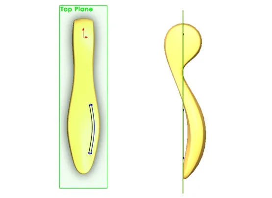
The first step is to use the TOP Plane to sketch out a few splines and tangent arcs. Below are side and top views with the plane and sketch visible.
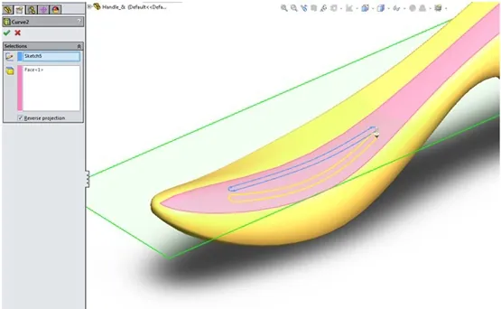
Next use the projected curve command to get the 2D slot shape to sort of well, project, itself down onto the surface:
Next, we will just copy the surface we want to start our cut on using the offset surface command with an offset value of 0. This is essentially a copy surface command. The result is a free-standing surface body that looks just like the original one on the solid model. This is a great way to keep the original solid model untouched while working on new geometry.

It will be on this surface that we will use the surface trim command. Select the previously created curve, and the surface created in the offset surface step, and then use the keep selections. The result is shown here:

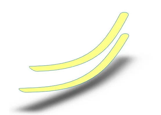
Then run a simple offset surface command. The offset value will end up being the depth of your hole.
Here we did a 6mm offset resulting in two surface bodies:
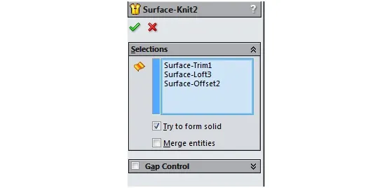
Run a surface loft from the top body down to the bottom body, knit the three surface bodies together and you will now have a solid body that looks like this:
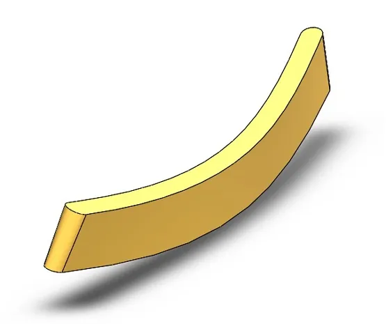
Note: Make sure to look at the solid bodies folder in the feature manager tree – some bodies may be hidden, and some bodies could have remained as surface bodies if you didn’t choose the Try to Form Solid option during your surface knit.
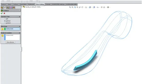
Finally, use the combine command with the subtract option to CUT this new solid body into the previous solid body: (initial solid body showing as blue outlines in the picture for clarity)
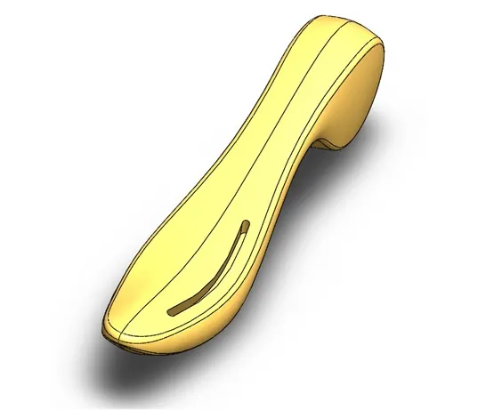
The final part:
There are many different ways to skin this cat. This was just one example. How many different ways do YOU know how to get this task done?

SOLIDWORKS CAD Cheat Sheet
Our SOLIDWORKS CAD Cheat Sheet, featuring over 90 tips and tricks, will help speed up your process.
Related SOLIDWORKS Tutorials
Creating Normal Cuts in SOLIDWORKS Sheet Metal
SOLIDWORKS FeatureWorks: Automatic vs. Interactive Recognition
Creating Multiple Parts from One Part File in SOLIDWORKS
SOLIDWORKS 2020 Structure Systems for Weldments
Propagating Assembly Features to Parts
Editor's Note: This post was originally published in August 2015 and has been updated for accuracy and comprehensiveness.

About Jesse Ortman
Jesse Ortman is an Engineering Manager at GoEngineer. When Jesse isn’t working with customers to solve their engineering challenges or keeping up on the latest SOLIDWORKS innovations, you will most likely find him riding his fat bike.
Get our wide array of technical resources delivered right to your inbox.
Unsubscribe at any time.